Knowledge

Electromagnetic interference on the industrial floor constantly puts the ruggedness of every field device to the test. How can the word "reliable" be more than just a claim on a datasheet? Solidot's answer: keep verification capability in-house. With its own 3-meter semi-anechoic chamber, Solidot now performs in-house EMC verification of its products, covering three core tests: RE radiated emission, RS radiated immunity, and CE conducted emission. RE and CE are emission tests, ensuring that a product's electromagnetic interference does not exceed the limits. RS is an immunity test, verifying that a product operates stably under external electromagnetic interference.
How are the tests actually performed? The following uses the measured procedures for three items - RE radiated emission, RS radiated immunity, and CE conducted emission - as examples.
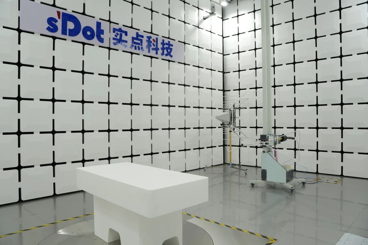
RE Radiated Emission Test
RE (Radiated Emission) test: The I/O module is placed on a turntable, which rotates 360°. A log-periodic antenna is mounted on a pneumatic antenna mast at a distance of exactly 3 meters from the module - which is where the name "3-meter method" comes from.
During the test, the antenna is raised and lowered within a range of 1 to 4 meters and switched between horizontal and vertical polarization to capture the maximum radiation point of the module in every direction. The signal is transmitted via RF cable to the control room, where it is detected and analyzed by a receiver and then output to a computer for display. This means every trace of electromagnetic noise radiated by the module is quantified and presented, and any exceedance has nowhere to hide.
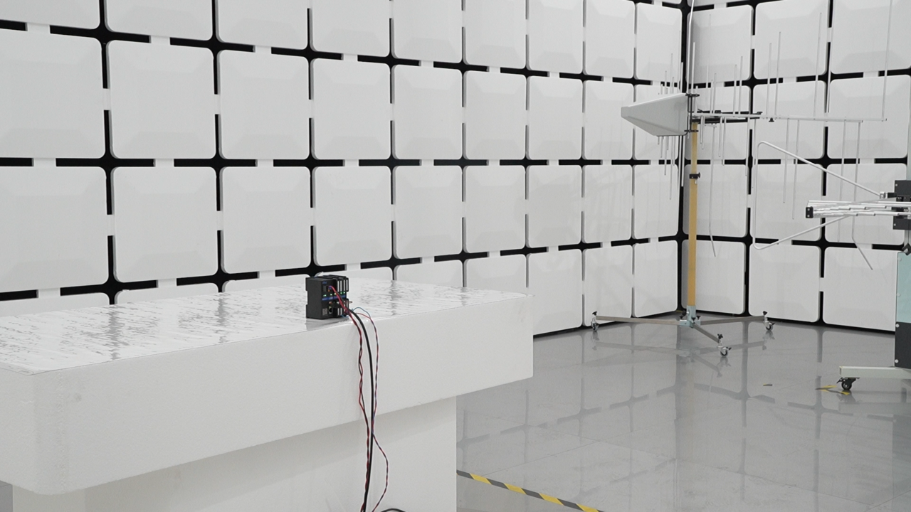
RS Radiated Immunity Test
RS (Radiated Susceptibility) test: The I/O module is likewise placed on a turntable, with a stacked log-periodic antenna 3 meters from the module. A signal generator outputs a swept-frequency signal, which is amplified by a power amplifier and drives the antenna to create a uniform interference field at the module's position.
During the test, the operating status of the I/O module is uploaded to the PLC via a Coupler, and a computer reads the PLC data in real time and, together with surveillance camera footage, displays the module's operating condition synchronously in the control room. The module must maintain uninterrupted communication and error-free data under continuous interference - a rigorous simulation of harsh conditions on the industrial floor.
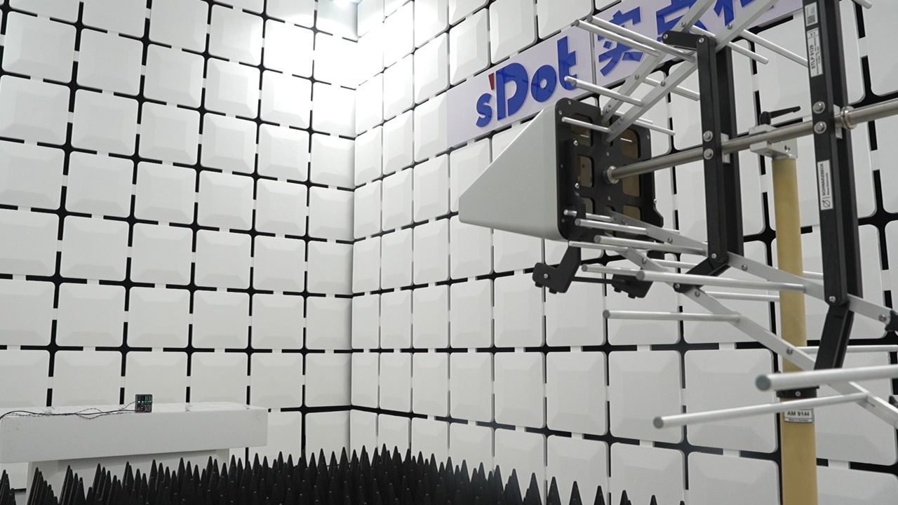
CE Conducted Emission Test
The CE (Conducted Emission) test is performed in the control room. The I/O module is placed on a table. A line impedance stabilization network (LISN) supplies clean power supply to the module on the one hand and picks up the interference signals generated by the module on the other, transmitting them to a receiver for detection and analysis, which finally outputs the test results.
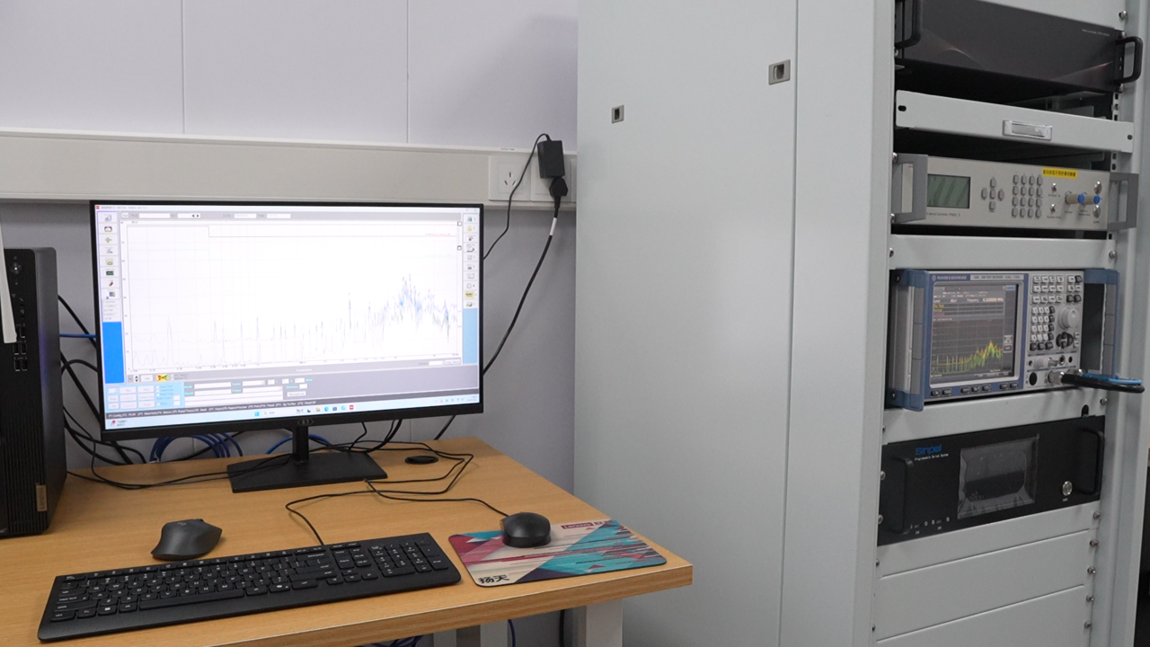
For users, the in-house chamber brings far more than testing convenience: the verification cycle is no longer limited by external lab scheduling, retesting can be done the same day after parameter adjustments, and products undergo more thorough and more intensive verification iterations before mass production - every I/O module delivered to the field has been tempered by this chamber before leaving the factory.
Once CNAS accreditation is completed in the future, the test data issued by the laboratory will carry third-party authoritative validity, providing stronger support for compliant product delivery. For Solidot, reliable is not a slogan but a system that can be verified.