Knowledge


When on-site faults such as load-side voltage not connected or abnormal output on an output channel occur, how can alarm information be seen immediately and handled in time? The Solidot 5 series integrated I/O modules provide two diagnostic functions to help users stay informed of alarms and quickly locate faults.
Each module supports two diagnostic functions. In the default version (default position of DIP switch 0), alarm information can be viewed in the configuration software in commissioning mode, meeting the needs of device commissioning and routine maintenance. The alarm version (DIP switch 0 set to ON) fully retains the diagnostic capability of the default version and additionally encodes the alarm code directly into the module's upstream data, so the PLC can read alarm information without the configuration software, enabling real-time monitoring and programmatic handling of alarms.
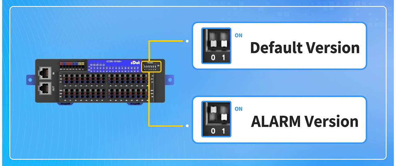
The diagnostic version of the module is determined by DIP switch 0: the default position is the default version, and ON is the alarm version. After switching versions, power cycle the entire module group for the new setting to take effect. The diagnostic capabilities of the two versions are compared below:
Comparison item | Default version | Alarm Version |
Alarm Viewing | Via the configuration software, view alarm information in debug mode | Covers all diagnostic capabilities of the default version |
Alarm Reading | Manual viewing via configuration software | Viewable via configuration software, the alarm code is additionally mapped into the upstream data, the PLC can read it directly |
Upstream data Area | No alarm code field | Includes alarm code field |
Application Scenarios | Debugging phase; applications with requirements for a continuous and regular I/O data area layout | Runtime monitoring; Applications requiring PLC-based programmatic alarm handling |
How to choose between the two versions?
The upstream data of the alarm version contains an additional alarm code field. Therefore, for applications that require a continuous, regular layout of the I/O data area, the data area of the default version is more streamlined; while for applications that require the PLC to read alarms directly and implement programmatic monitoring and handling, the alarm version is more convenient.
How to use the two versions?
1. Default version
No additional configuration is required. Enter commissioning mode in the configuration software to view module alarm information on the alarm information page, making it easy to quickly confirm alarm status during commissioning and routine maintenance.
2. Alarm version
With the alarm code encoded into the upstream data, the PLC can obtain alarm information just like reading ordinary I/O data and implement programmatic handling on that basis:
● operation monitoring: When a fault occurs, the alarm code is reported in real time, so the PLC perceives the on-site abnormality immediately
● Programmatic handling: Execute logic such as alarm notification and interlock control based on the alarm code, without manual module-by-module inspection
● Reduced dependence on configuration software: Module alarm status can be monitored without opening the configuration software
The alarm codes cover common fault scenarios such as load-side voltage not connected, abnormal output on an output channel, firmware error and parameter setting error, and are divided into two categories:
● protocol alarm code: Alarms related to protocol communication
● process data alarm code: Alarms related to the on-site process (e.g. load-side voltage not connected)
This concludes the introduction to the dual-channel diagnostic function of the Solidot 5 series integrated I/O. If you have any questions, please feel free to contact us. We will be glad to be of service!