Solidot IO-Link Bus I/O and Laser Distance Sensor Application Guide

The IOL7-PN01B-8A-1, as Solidot's IO-Link master station, features 8 IO-Link ports compliant with IO-Link Standard V1.1. It supports up to 8 Class-A IO-Link slave devices, compatible with both Solidot IO-Link Hubs and third-party standard IO-Link slaves. Below demonstrates its integration with the SICK Dx35 laser distance sensor.
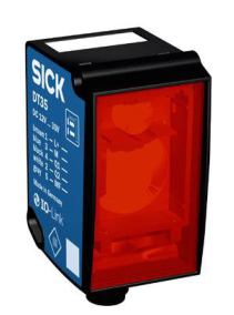
SICK Dx35 Laser Distance Sensor
Supports IO-Link protocol
Connects to Solidot IO-Link Bus I/O master for real-time distance value reading
I. Wiring Method
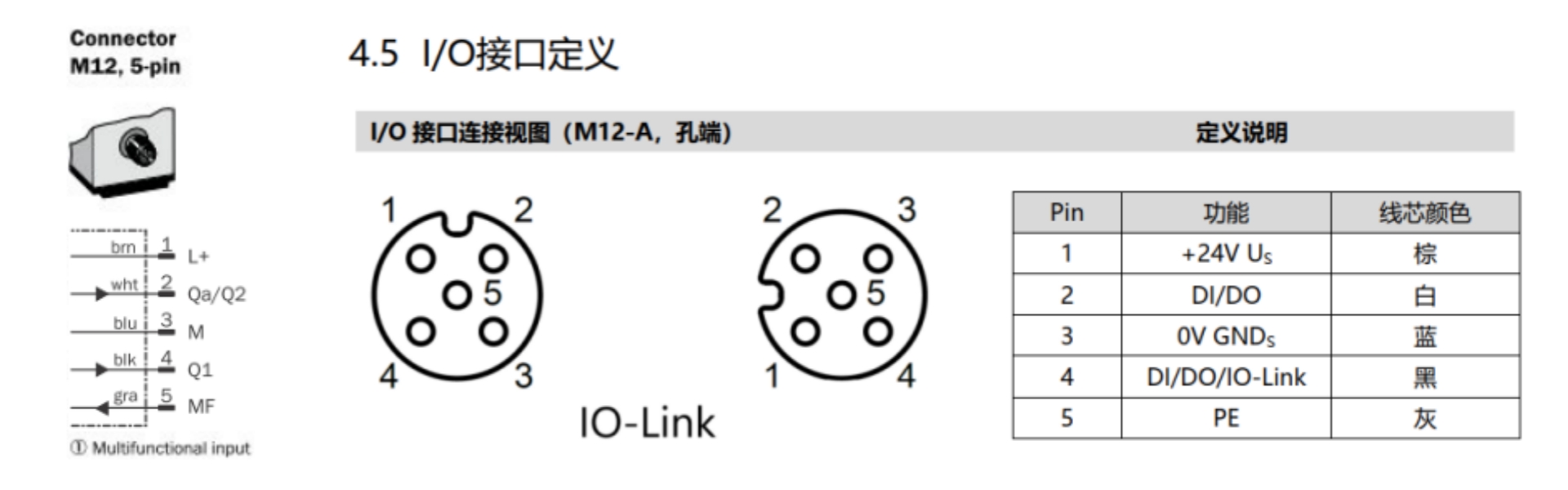
Left: Sensor Interface | Right: IOL7-PN01B-8A-1 Interface
The sensor uses a standard M12 A-Code interface. Connect directly via Solidot’s pre-molded cable CZG/CZM-1.0CS (1m, shielded black).
II. Software Configuration (TIA Portal)
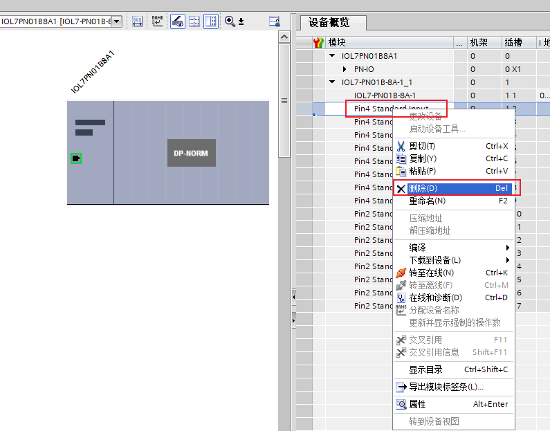
Add the IOL7-PN01B-8A-1 module in configuration; it auto-generates slots:
Pin4 Standard Input
Pin2 Standard Input
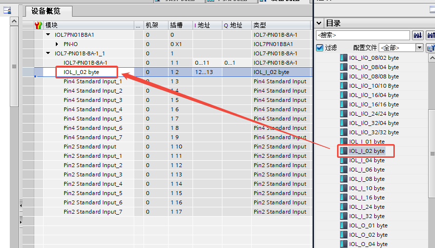
Per sensor manual, process data requires 2-byte input. Since the slave connects to master port X00:
Delete first "Pin4 Standard Input"
Replace with IOL_I_02 byte
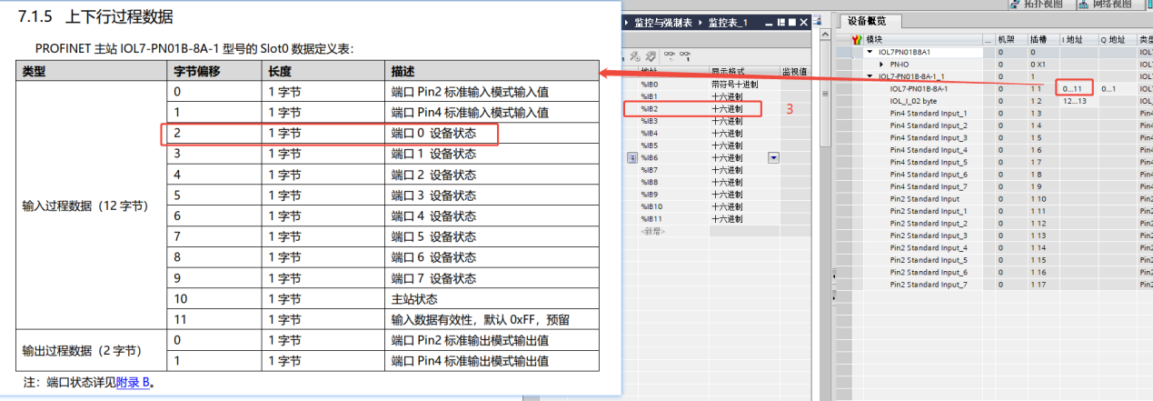
Monitor addresses IB0–IB11 in watch tables:
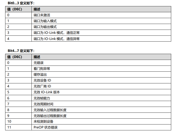
IB2 = 3 indicates successful sensor connection
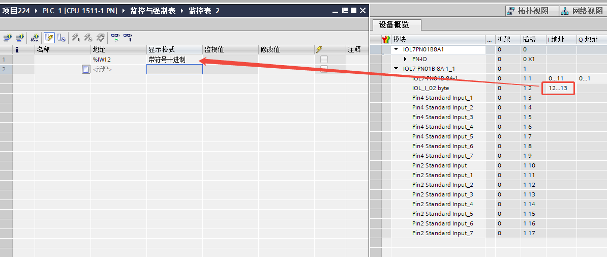
Distance values are stored at IW12:
Monitor IW12 with "Signed Decimal" format for real-time distance data
For further inquiries, contact Solidot technical support.