Configuration Method for Solidot Distributed I/O XBF4-EC04 Coupler on Keyence KV Series PLCs
The Keyence KV Series PLC features an innovative motor control Universal Library, supports the IEC 61131-3 international PLC programming standard, and includes an operation recording function that captures all variables/all soft elements/camera/event data during faults. Below describes the parameter configuration method for the Solidot Distributed I/O XBF4-EC04 Coupler on the Keyence KV platform.
I. Configuring Slot Models
Example:
XBF Interface 1 connects 2 I/O modules:
Model XBF2E-0808A (DIP switch station address: 0)
Model XBF2E-0016A (DIP switch station address: 4)
XBF Interface 2 connects 1 I/O module:
Model XBF2E-0808A (DIP switch station address: 1)
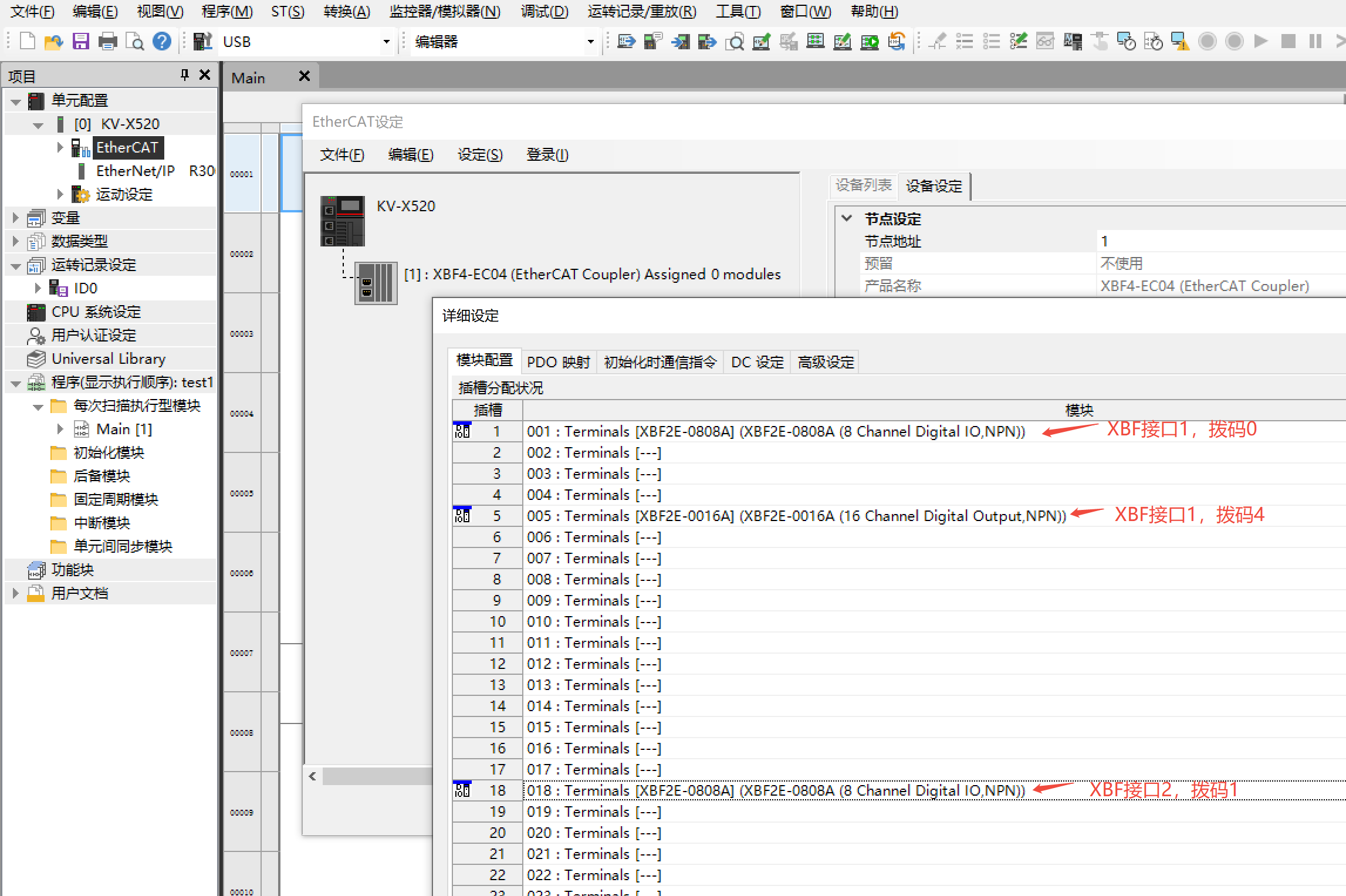
Note:
The XBF4-EC04 Coupler has 4 XBF interfaces with 64 slots total.
Each XBF interface supports serial connection of up to 16 I/O modules (DIP switch addresses 0~F, must be unique).
Single coupler supports expansion of up to 32 XBF series I/O modules.
Slot Allocation:Slots 1-16: XBF Interface 1
Slots 17-32: XBF Interface 2
Slots 33-48: XBF Interface 3
Slots 49-64: XBF Interface 4
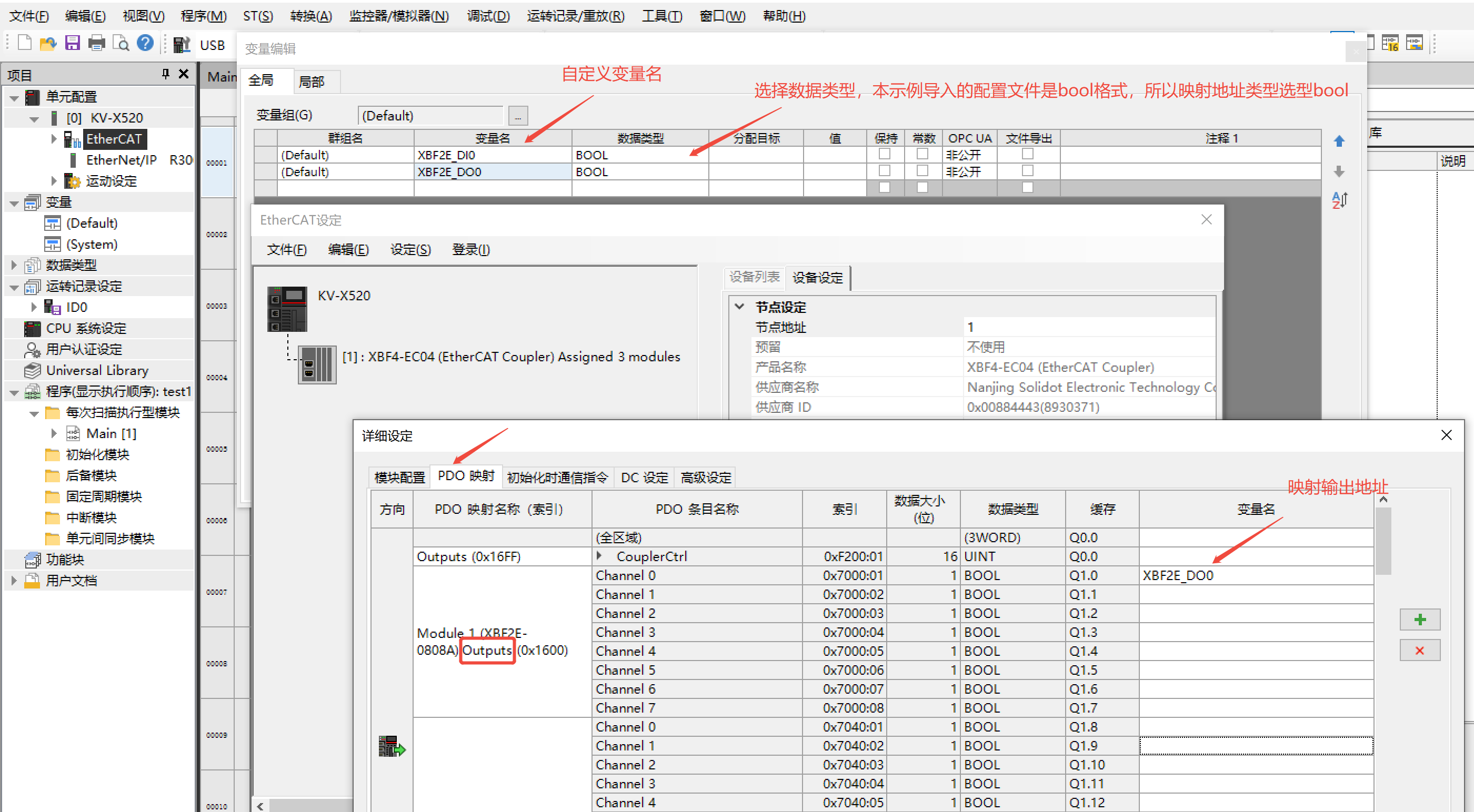
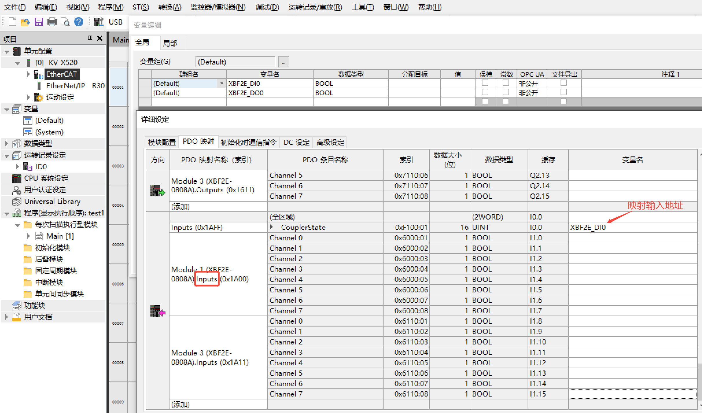
II. Input/Output Address Mapping
1.Output Address Mapping
2.Input Address Mapping
III. Parameter Configuration
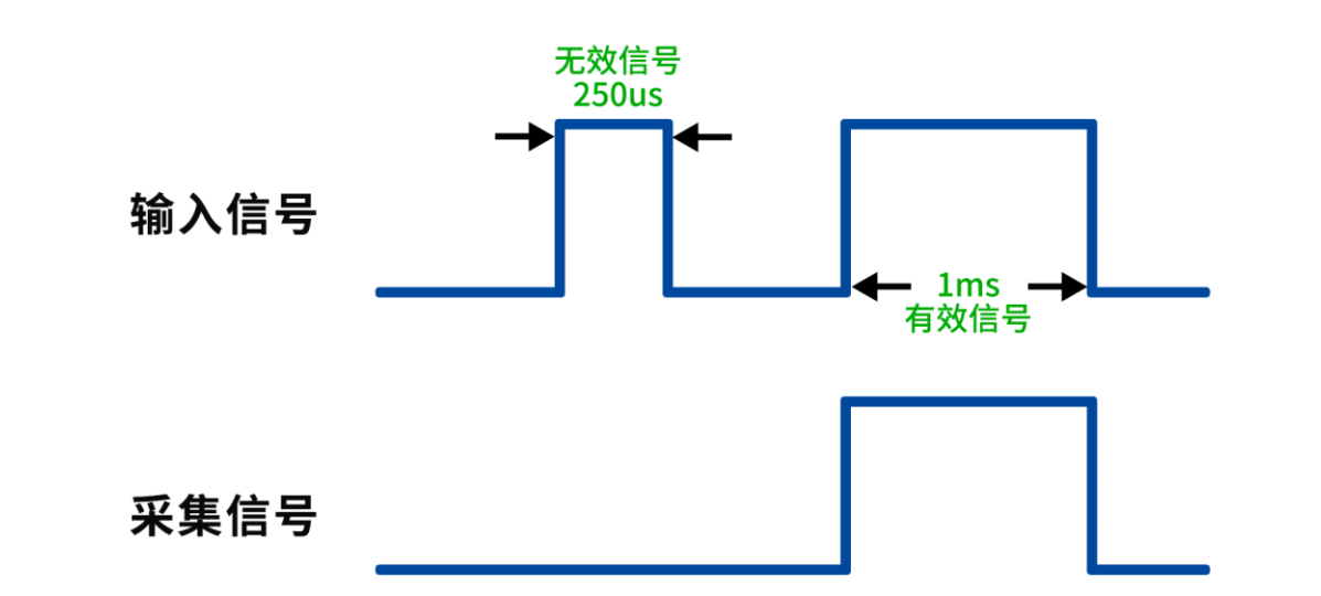
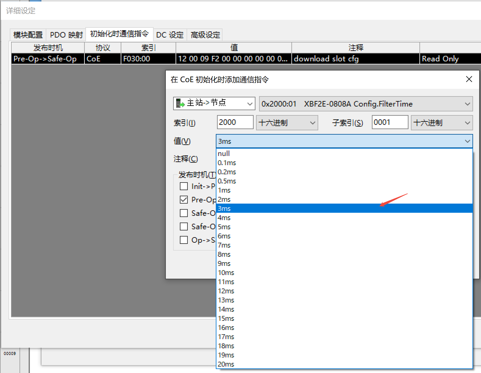
1. Digital Input Filter Parameters
Digital input filtering prevents program responses to unintended rapid signal changes caused by contact bounce or electrical noise.
Configurable per module (not per channel).
Default filter time: 3ms.
Supported range: No filter, 0.1ms, 0.2ms, 0.5ms, 1ms, 2ms, 3ms (factory default), 4ms..18ms, 19ms, 20ms.
Functionality:A 3ms filter blocks noise pulses shorter than 3ms.
Signal transitions (0→1 or 1→0) must persist ≥3ms to be detected.
Example: When configured to 1ms, a 250μs pulse is rejected as invalid.
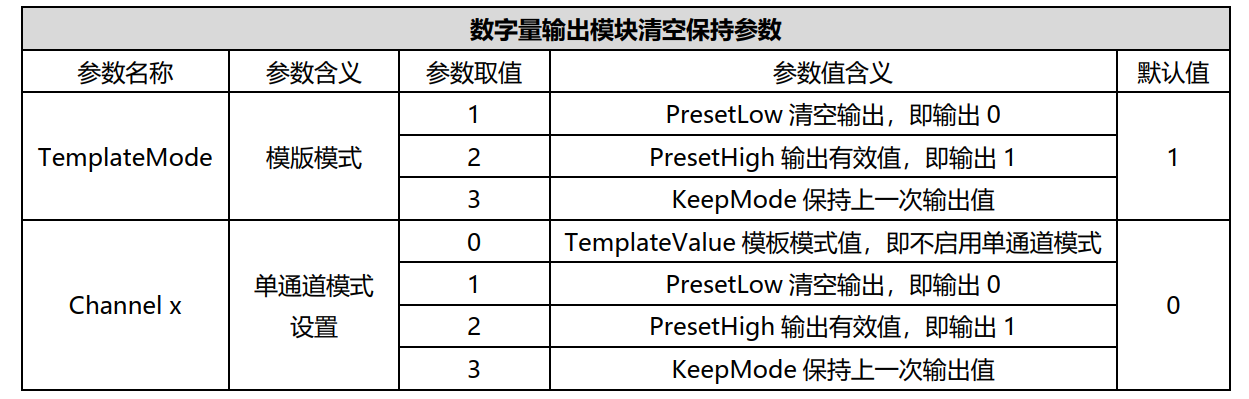
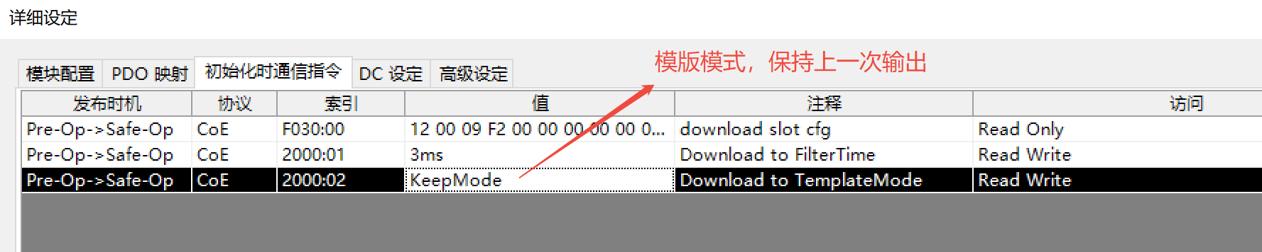
2. Digital Output Clear/Hold Parameters
Configures output channel behavior during non-Operational (OP) states (e.g., PLC stop or coupler network disconnection).
Supported modes:
Clear Outputs: Outputs reset to 0.
Output Valid Value: Outputs maintain 1.
Hold Last Value: Outputs retain pre-fault state.
Configuration Modes:
Template Mode (default): Applies single setting to all channels.
Single-Channel Mode: Per-channel override.
Single-Channel Mode has higher priority than Template Mode.
Default: Template Mode → Clear Outputs.
IV. Configuration Procedure Example
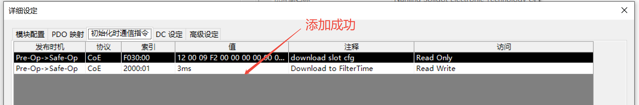
1. Initialization Communication Command
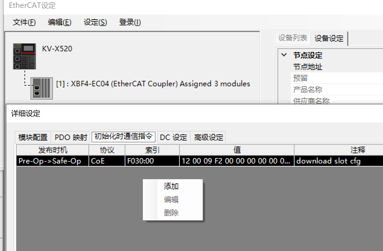
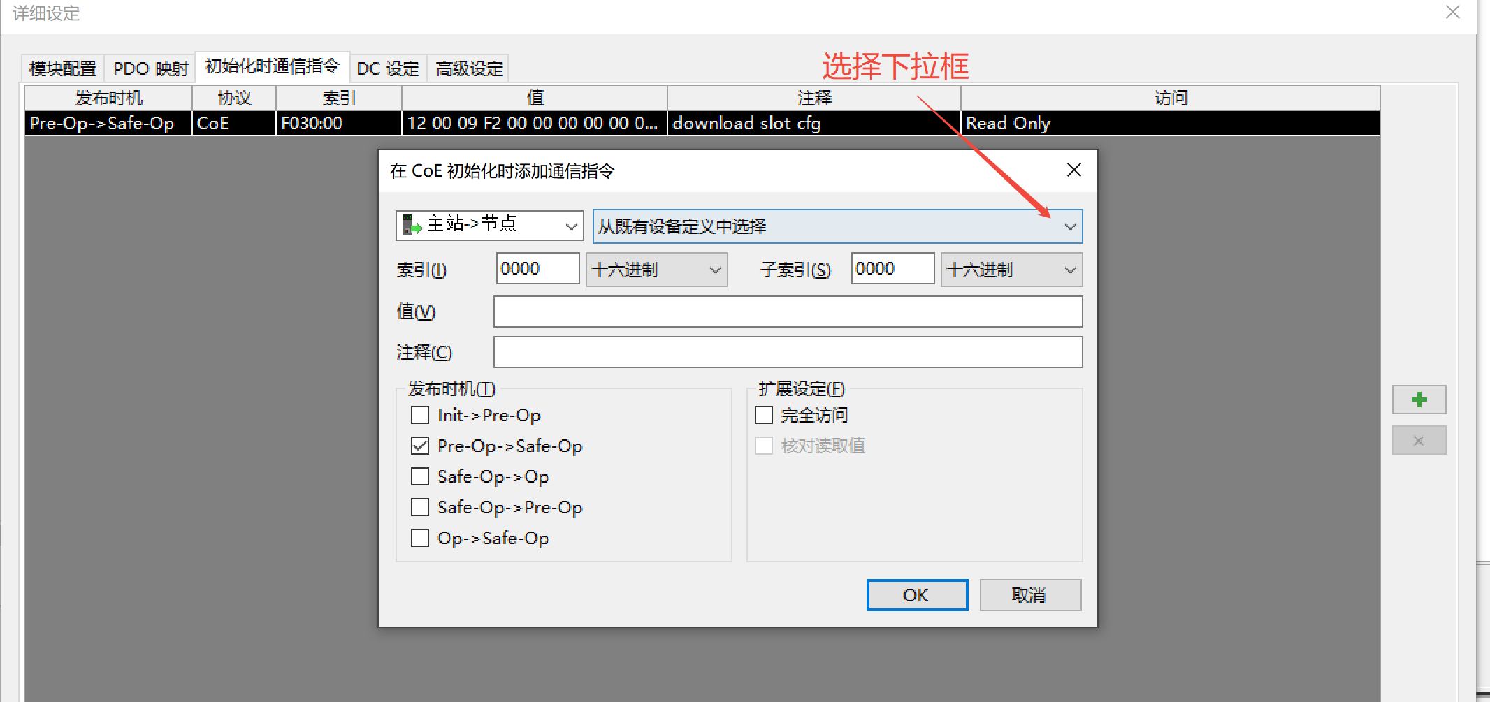
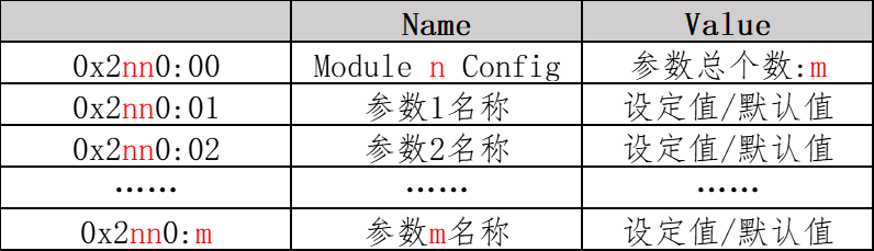
nn: Slot number (0x00 to 0x3F, corresponds to expanded I/O modules).m: Parameter index of the module.
2. Configure DI Filter Parameter
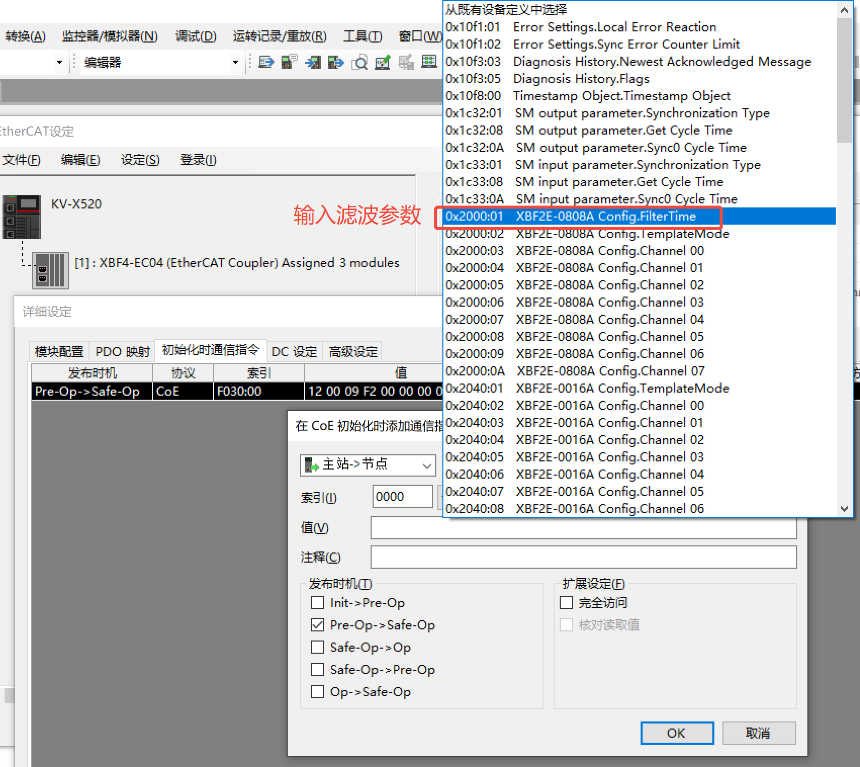
Default: 3ms. Adjust as needed.
3. Configure DO Clear/Hold Parameter
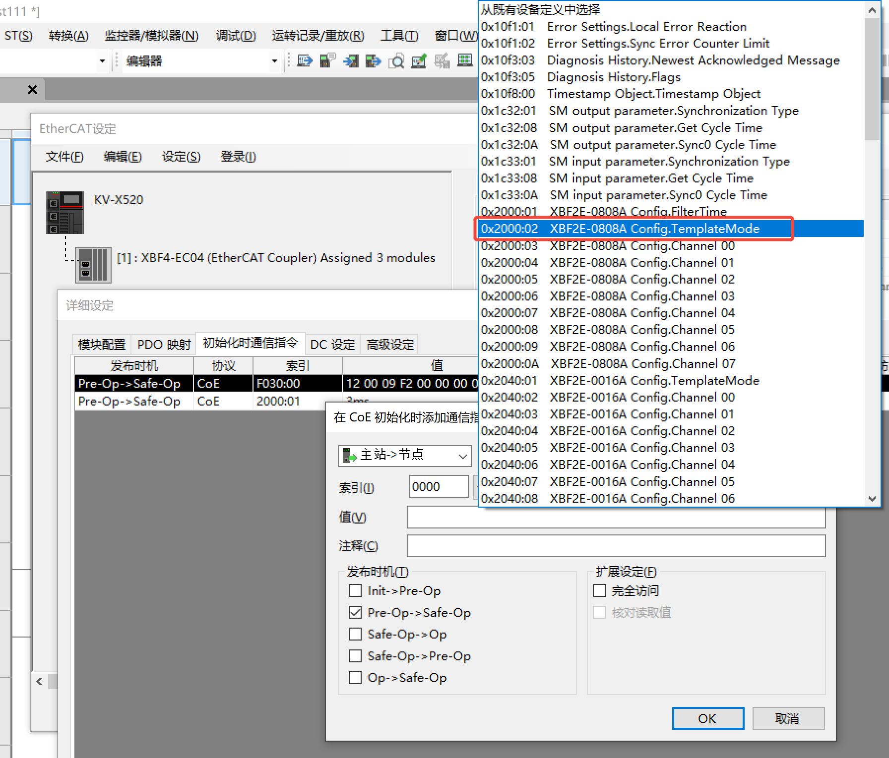
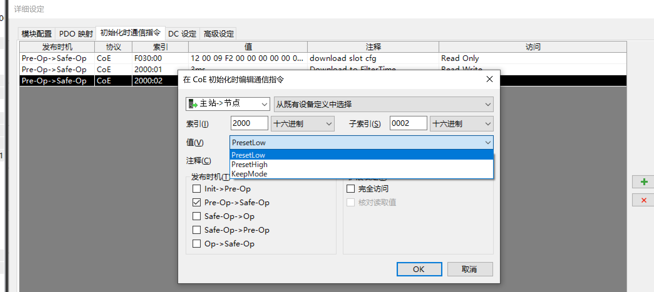
Template Mode (default = 1):
1: Clear Outputs2: Output All 13: Hold Last Value
Single-Channel Mode (default = 0):
0: Use Template Mode1: Single-Channel Clear Output2: Single-Channel Output 13: Single-Channel Hold Last Value
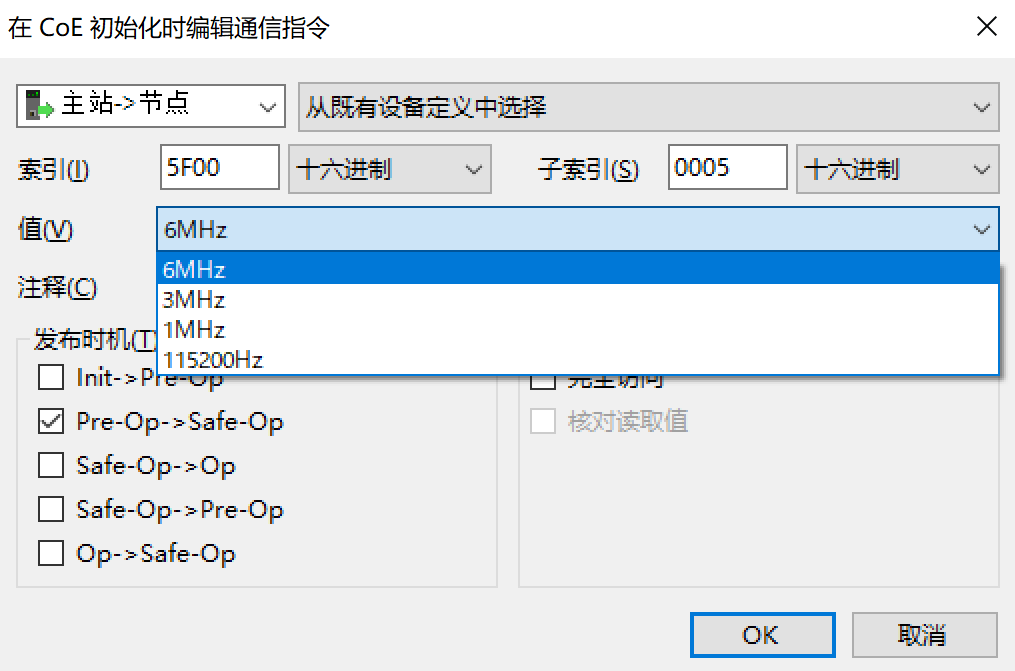
4. Bus Baud Rate Setting
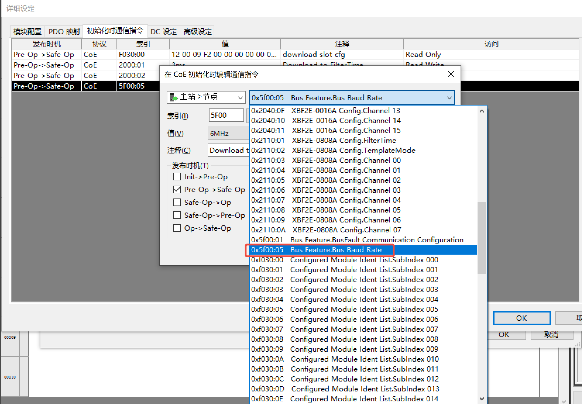
Default: 6MHz. Adjust as needed.
Conclusion
This document details the parameter configuration method for the Solidot Distributed I/O XBF4-EC04 Coupler on Keyence KV Series PLCs. For further assistance, please contact our technical support team.