Calculation of upstream and downstream byte lengths and address allocation method for IO modules under Ethernet/IP protocol

↑Solidot Technology EtherNet/IP Coupler Kit XB6-EI2002ST
1. Digital I/O Module under EtherNet/IP Protocol
Each module is allocated a 4-byte data unit, each channel occupies 1 bit, and the actual data length used varies depending on the number of module channels.
2. Analog I/O Module under EtherNet/IP Protocol
Each module is allocated a 16-byte data unit, each channel occupies 2 bytes, and the actual data length used varies depending on the number of module channels.
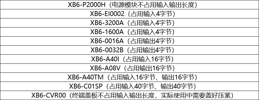
The data length allocation is as follows:
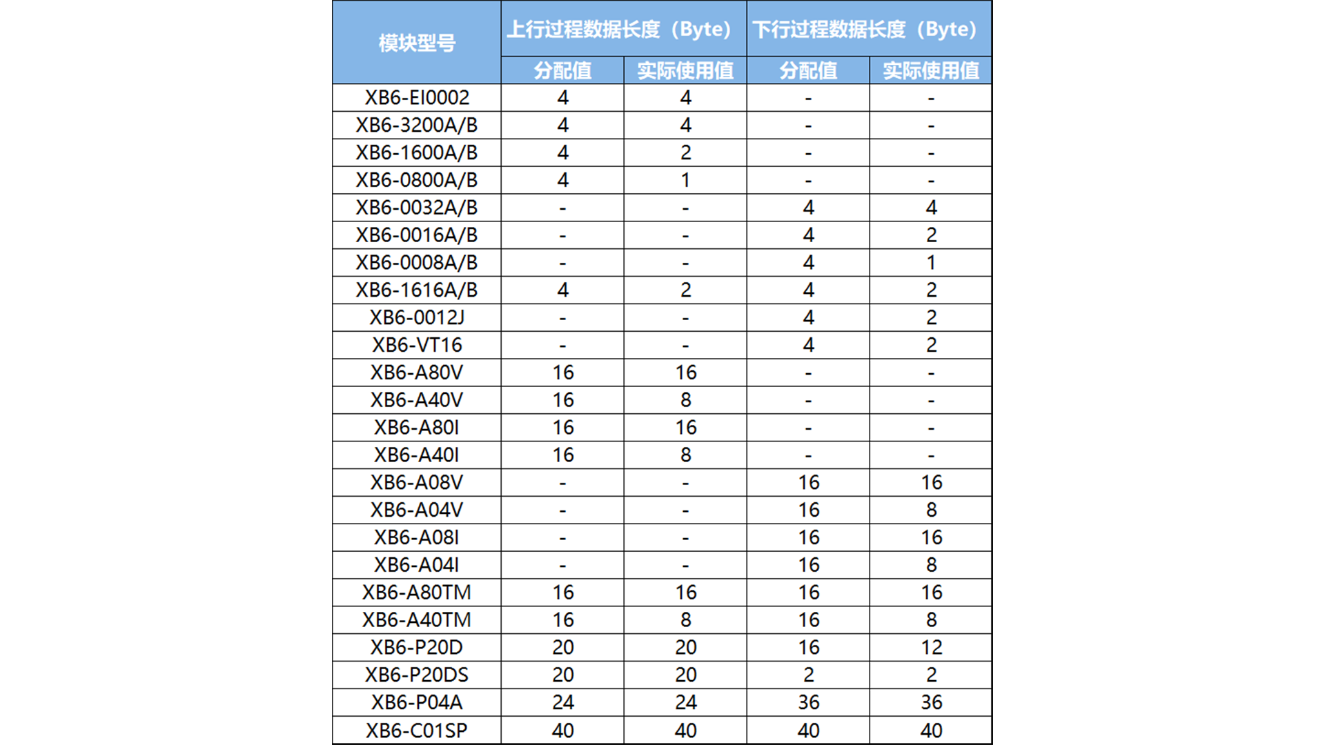
Note: The length of the upstream and downstream bytes is calculated according to the allocated value. If the module allocation value is greater than the actual value, the extra byte address is reserved and has no practical meaning. For example, XB6-1600A needs to allocate an upstream 4-byte address, and the actual 16 points occupy an upstream 2-byte address, and the extra upstream 2-byte address is reserved.
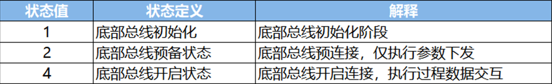
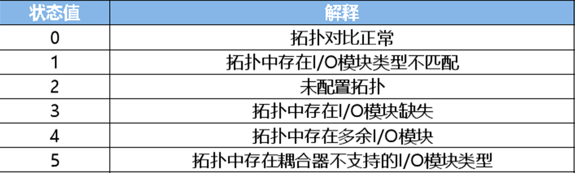
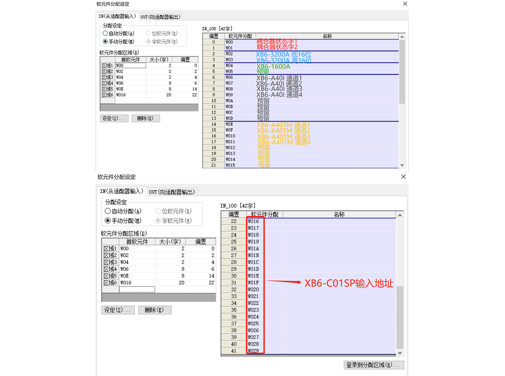
The coupler allocates 4 bytes of data for coupler status indication and alarm, definition of bottom bus status indication and topology comparison prompt. The coupler occupies the first 4 bytes of the uplink (input) address. The feedback words for normal communication status are 4 and 0.
Bottom bus status prompt——
Topology status comparison status prompt——
Example:
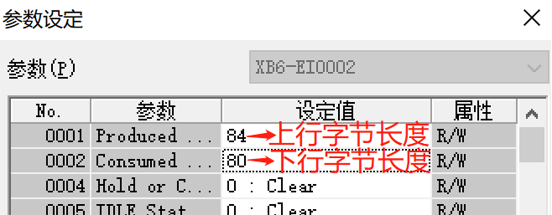
1. Taking the Keyence master station as an example, the configuration calculates the uplink (input) and downlink (output) byte lengths of the following modules:
To sum up, the uplink byte length is 84, and the downlink byte length is 80
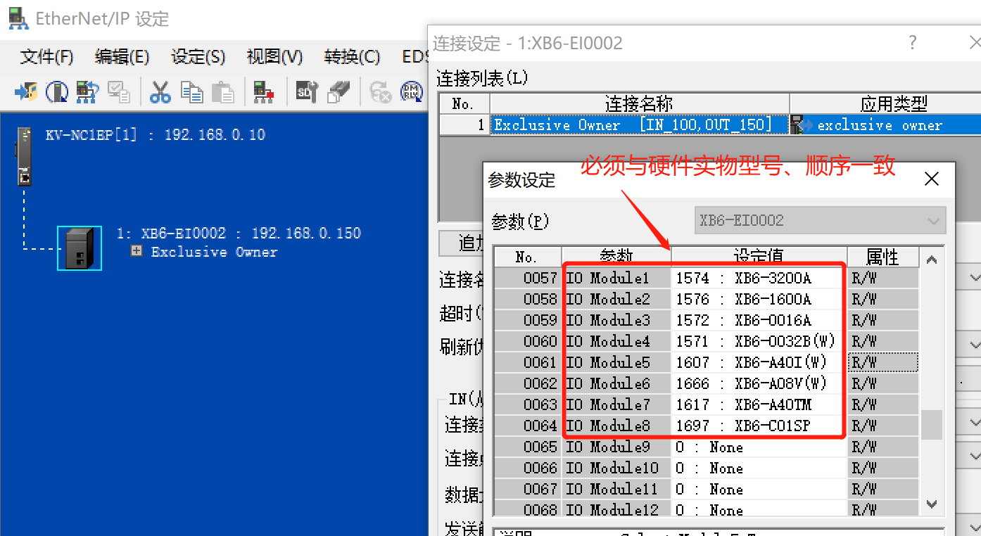
2. Configure the I/O Module, and the model and position must be consistent with the actual object:
3. Uplink address allocation:
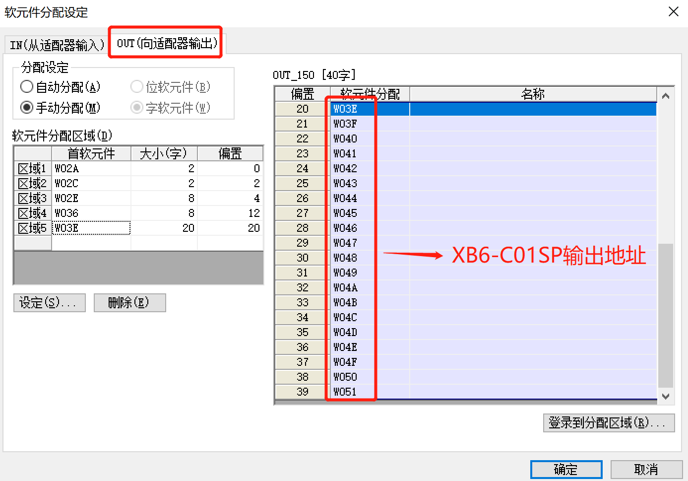
4. Downlink address allocation:
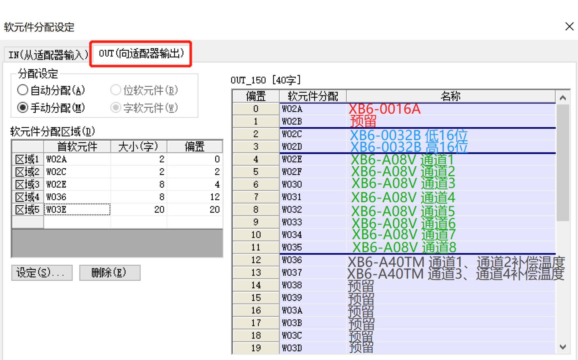
Note: The lower 8 bits of W036 are the compensation temperature of XB6-A40TM channel 1, and the upper 8 bits are the compensation temperature of XB6-A40TM channel 2; the lower 8 bits of W037 are the compensation temperature of XB6-A40TM channel 3, and the upper 8 bits are the compensation temperature of XB6-A40TM channel 4.