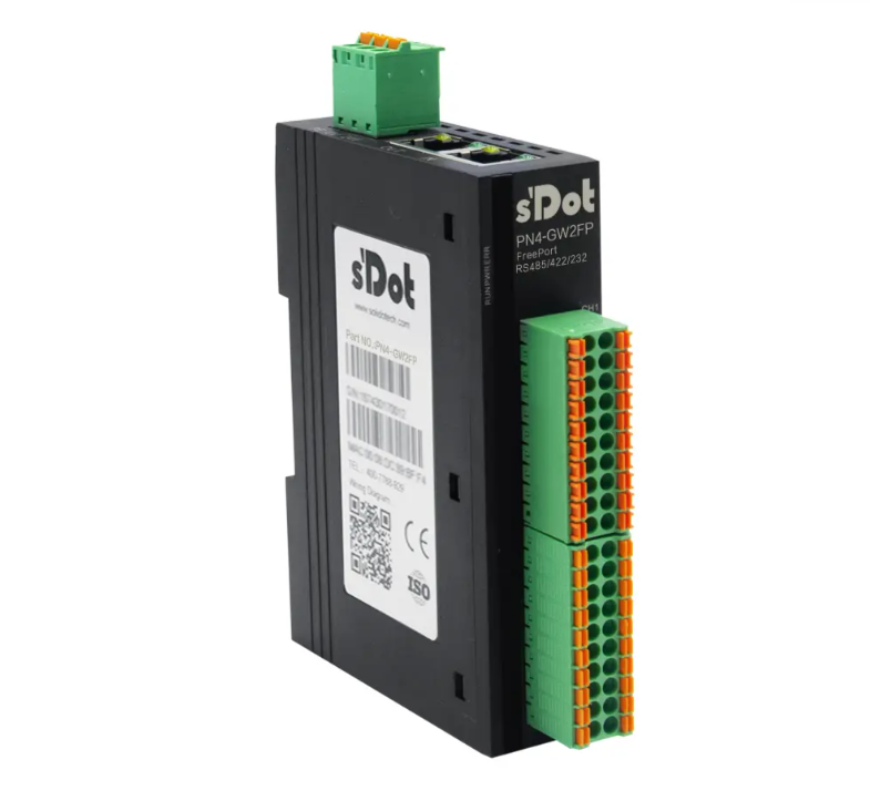
PN4-GW2FP Multi-Scenario Application Introduction Under Producer-Consumer Model
The PN4-GW2FP is an integrated gateway module from Solidot for converting PROFINET to Freeport (Serial Port). The data transmission methods in serial communication's Freeport protocol can be primarily divided into two categories: Continuous Transmission and Command-Based Transmission (Query-Response). This article details the configuration and application steps of the PN4-GW2FP module under different scenarios.
I. Preparations
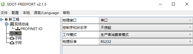
Download the Solidot PN4-GW2FP configuration software "SDOT-FREEPORT", create a new project, select "Producer-Consumer Model" as the working mode, and choose the physical standard based on the actual situation. In this example, a USB-to-RS232 serial cable is used, so "RS232" is selected.
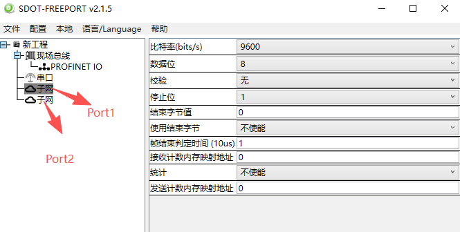
The "Subnet" requires configuring parameters for the connected serial device, such as Baud Rate, Data Bits, Parity, and Stop Bits. Other parameters can be left as default.
II. Producer Mode Configuration
The Producer, also known as the Request, is an output for the module. It transmits specified data from the fieldbus network (PROFINET) to the serial device.
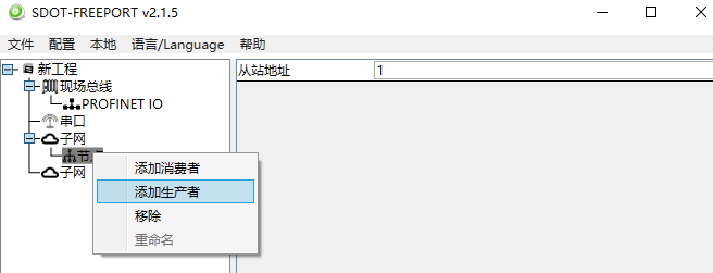
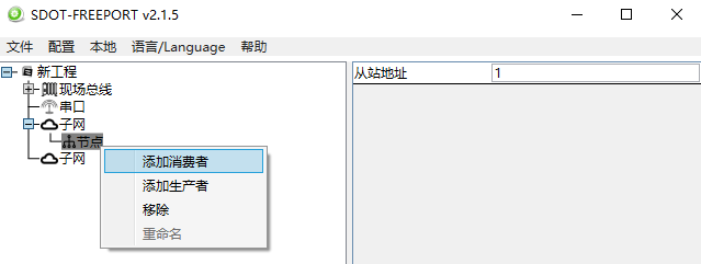
Right-click the "Subnet" to add a "Node", then right-click the "Node" to add a "Producer". Keep the slave address as the default value of 1 (currently non-functional).
Example: Producer Mode Application Scenario (I)
Continuously sending (outputting) data at a set cycle time.
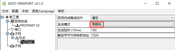
Send Mode Selection: Periodically. Sends data frames cyclically at intervals based on the Send Delay time (10ms). For example, the default parameter 100 corresponds to an interval of 100 x 10 = 1000ms for periodic sending.
Send Delay (10ms): 100. Sends data periodically at 1000ms intervals.
Trigger Byte Memory Mapping Address: Default 1500. This parameter is invalid when the send mode is "Periodically".
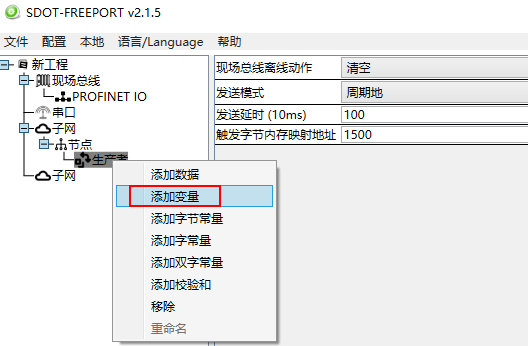
Right-click the "Producer" to add "Variable" data.
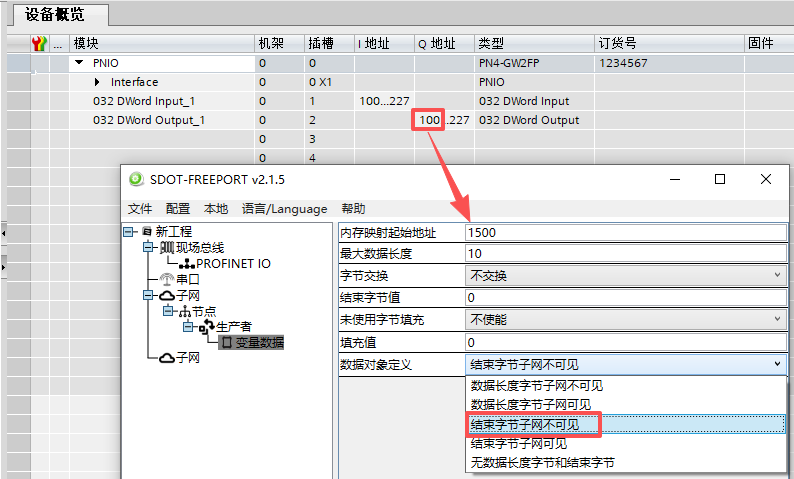
The data conversion between the PROFINET network and the serial port in PN4-GW2FP is established through a "mapping" relationship. The PN4-GW2FP has two data buffers: one is the Input Buffer (1500 bytes) with an address range of 0-1499; the other is the Output Buffer (1500 bytes) with an address range of 1500-2999.
Memory Mapping Start Address: 1500. This corresponds to the starting QB address in TIA Portal. In this TIA Portal example, it is QB100.
Max Data Length: 10 bytes. This corresponds to TIA Portal addresses QB100-QB109. (Note: If the Memory Mapping Start Address is configured as 1502, it corresponds to TIA Portal addresses QB102-QB111. Important: The address length allocated in TIA Portal can be greater than or equal to the Max Data Length configured in the software).
Data Object Definition: End Byte Subnet Invisible.
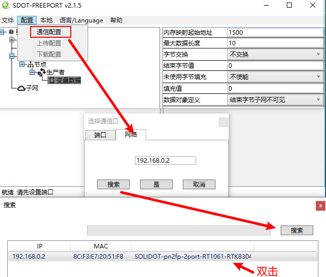
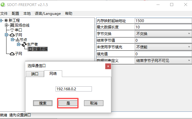
Download Configuration: Configuration - Communication Config - Network - Search - Double-click the module found, then click "Yes".
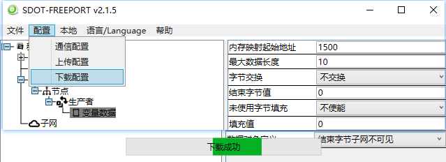
Configuration - Download Configuration.
Monitoring: Data is sent cyclically at the set 1000ms interval.
Example: Producer Mode Application Scenario (II)
Sending (outputting) data once based on a command.
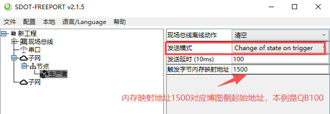
Send Mode Selection: Trigger data change (change of state on trigger). Sends data once when the trigger byte data in the memory mapping address changes.
Send Delay (10ms): 100. Sends data after a delay of 100x10=1000ms following the change of the trigger byte data.
Trigger Byte Memory Mapping Address: Default 1500. This corresponds to the starting QB address in TIA Portal. In this example, it is QB100.
Right-click the "Producer" to add "Variable" data.
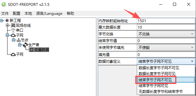
Memory Mapping Start Address: 1501 (Must not conflict with the Trigger Byte Memory Mapping Address set above). This corresponds to the QB address in TIA Portal. In this TIA Portal example, it is QB101.
Max Data Length: 10 bytes. This corresponds to TIA Portal addresses QB101-QB110.
Data Object Definition: End Byte Subnet Invisible.
The configuration download method is the same as above.
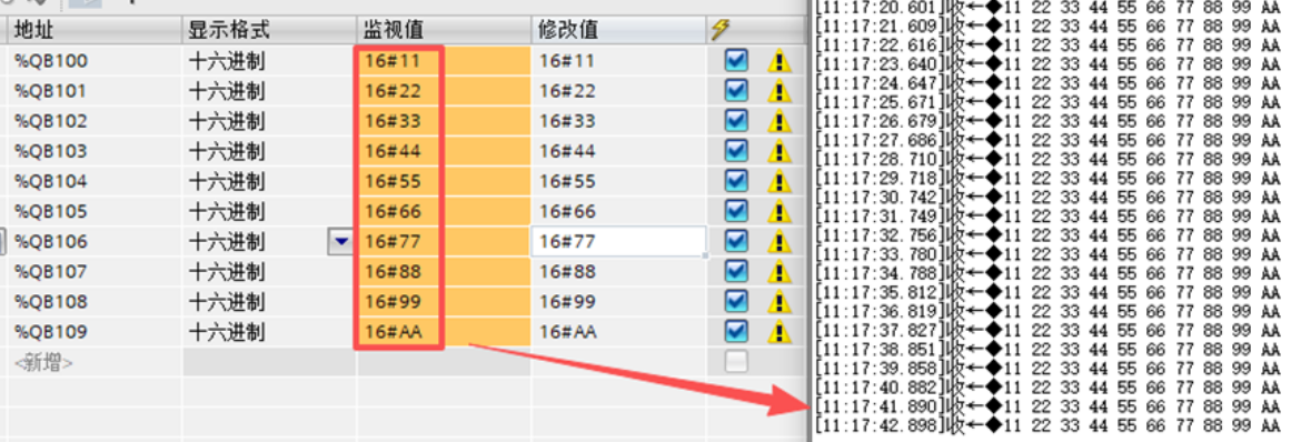
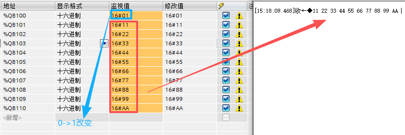
Monitoring: Modify the value of QB100 (0 -> 1) to send data once.
Modify the value of QB100 (1 -> 2) to send data again.
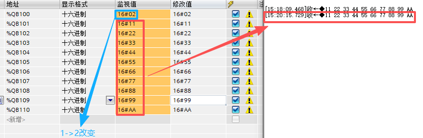
Data is sent once every time the value of the Trigger Byte Memory Mapping Address is modified.
III. Consumer Mode Configuration
The Consumer, also known as the Response, is an input for the module. It transmits specified data from the serial device to the fieldbus network (PROFINET).
Right-click the "Subnet" to add a "Node", then right-click the "Node" to add a "Consumer". Keep the slave address as the default value of 1 (currently non-functional).
Example: Consumer Mode Application Scenario (I)
Only responsible for receiving (inputting) data.
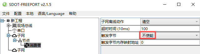
Subnet Offline Action: Selects how data sent to the fieldbus is affected when the subnet goes offline.
Clear: Clears the data at the PROFINET IB address after the subnet goes offline.
Hold: Holds the data at the PROFINET IB address after the subnet goes offline.
Timeout (10ms): Specifies the maximum allowed time between two received data packets. If this time is exceeded, the subnet is considered offline and timeout, and the set Subnet Offline Action will be executed. For example, setting 100 means a timeout of 10 x 100 = 1000ms.
Trigger Byte: Disabled.
Trigger Byte Memory Mapping Address: Default 0. This parameter is invalid when the Trigger Byte is "Disabled".
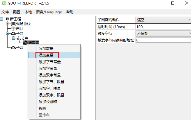
Right-click the "Consumer" to add "Variable" data.
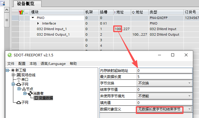
Memory Mapping Start Address: 0. This corresponds to the starting IB address in TIA Portal. In this TIA Portal example, it is IB100.
Max Data Length: 5 bytes. This corresponds to TIA Portal addresses IB100-IB104. (Note: If the Memory Mapping Start Address is configured as 4, it corresponds to TIA Portal addresses IB104-IB108. Important: The address length allocated in TIA Portal can be greater than or equal to the Max Data Length configured in the software).
Data Object Definition: No Data Length Byte and End Byte.
The configuration download method is the same as above.
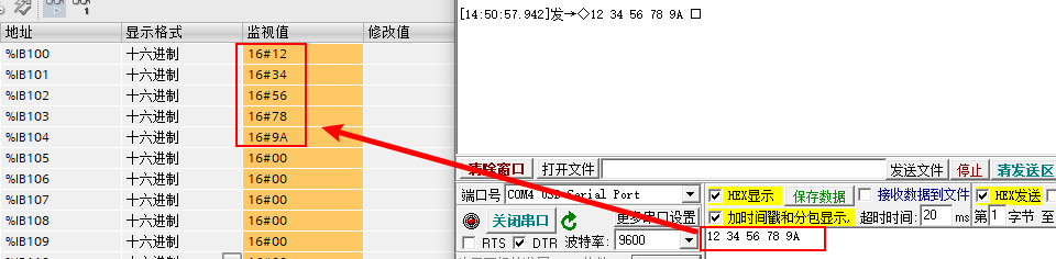
Monitoring:
Example: Consumer Mode Application Scenario (II)
Responsible for receiving (inputting) data and recording the number of receptions.
Subnet Offline Action: Selects how data sent to the fieldbus is affected when the subnet goes offline.
Clear: Clears the data at the PROFINET IB address after the subnet goes offline.
Hold: Holds the data at the PROFINET IB address after the subnet goes offline.
Timeout (10ms): Specifies the maximum allowed time between two received data packets. If this time is exceeded, the subnet is considered offline and timeout, and the set Subnet Offline Action will be executed. For example, setting 100 means a timeout of 10 x 100 = 1000ms.
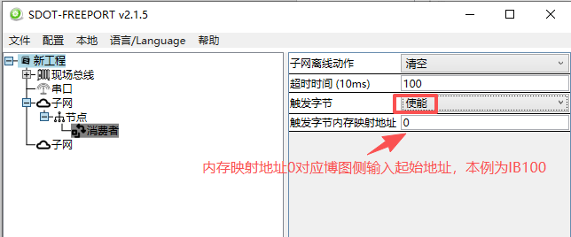
Trigger Byte: Enabled. Enabling the trigger byte requires specifying a byte location in the "Trigger Byte Memory Mapping Address". If enabled, a new change byte is added when data is received and responded to, which can be used by the serial module to count the number of received data packets.
Trigger Byte Memory Mapping Address: 0. This corresponds to the starting IB address in TIA Portal. In this example, it is IB100.
Right-click the "Consumer" to add "Variable" data.
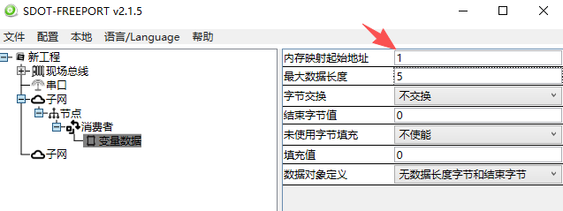
Memory Mapping Start Address: 1 (Must not conflict with the Trigger Byte Memory Mapping Address set above). This corresponds to the IB address in TIA Portal. In this TIA Portal example, it is IB101.
Max Data Length: 5 bytes. This corresponds to TIA Portal addresses IB101-IB105. (Note: If the Memory Mapping Start Address is configured as 4, it corresponds to TIA Portal addresses IB104-IB108).
Data Object Definition: No Data Length Byte and End Byte.
The configuration download method is the same as above.
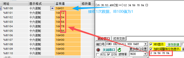
Monitoring: When the serial assistant sends data once, IB100 counts 1 reception, and IB101-IB105 show the received data.
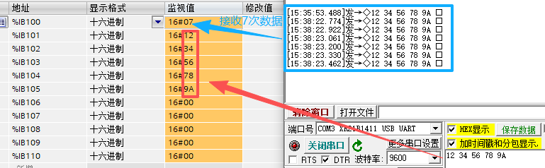
When the serial assistant sends data seven times, IB100 counts 7 receptions, and IB101-IB105 show the received data.
The above is the introduction to the multi-scenario applications of the PN4-GW2FP in the Producer-Consumer model. Thank you for watching!