Introduction to the Configuration of Solidot Remote I/O Serial Communication Module XB6S-C01SP in Modbus Communication
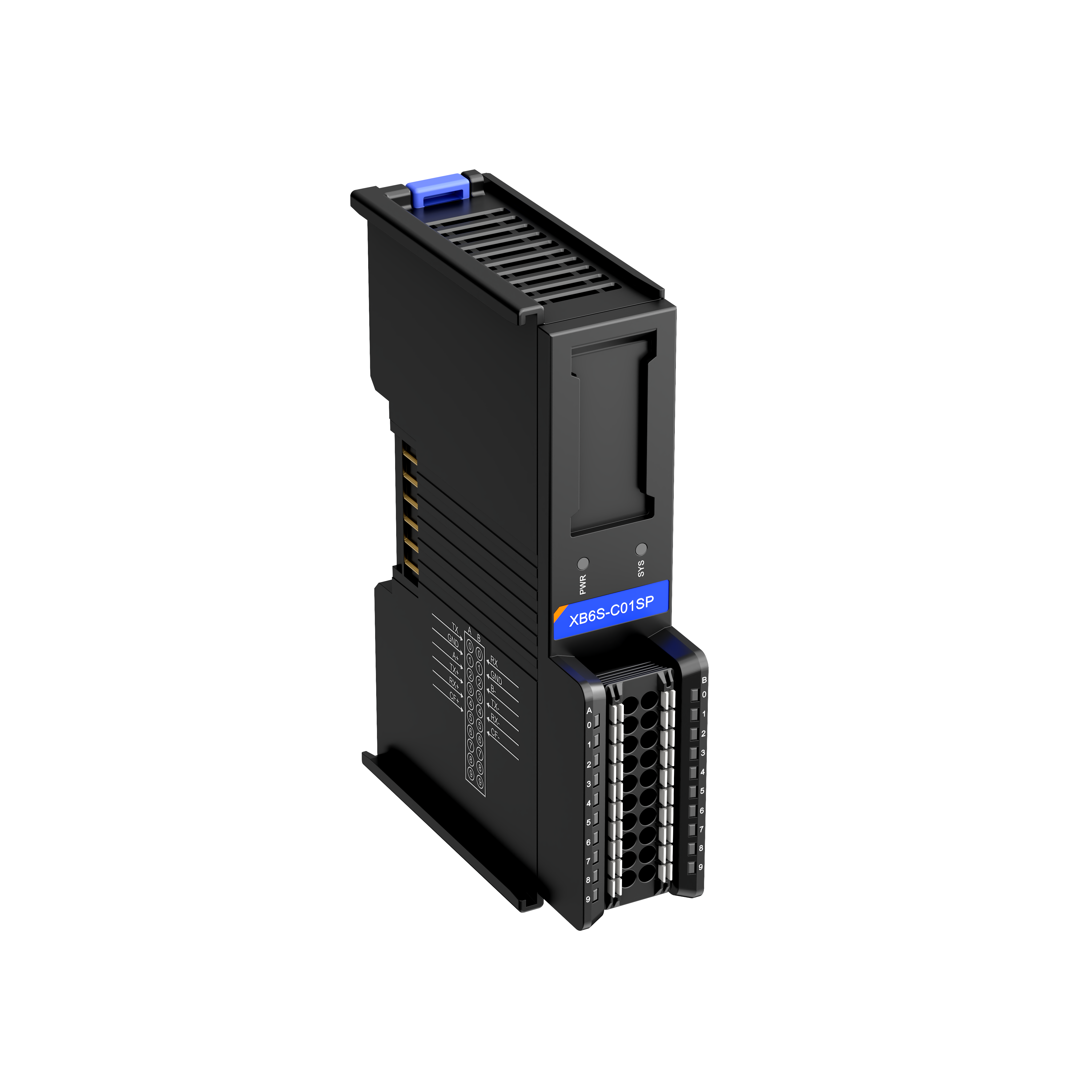
The XB6S-C01SP is a 1-channel serial communication module from Solidot's Remote I/O XB6S series, compatible with XB6S series couplers. This module features a compact design and simple configuration, making it suitable for various serial communication applications. This article mainly introduces its configuration steps in Modbus communication, as detailed below:
1. Serial Port Parameter Settings
When connecting to a physical serial port (including RS-232/485/422), the following parameters need to be configured: baud rate, stop bits, character format, parity bit, etc.
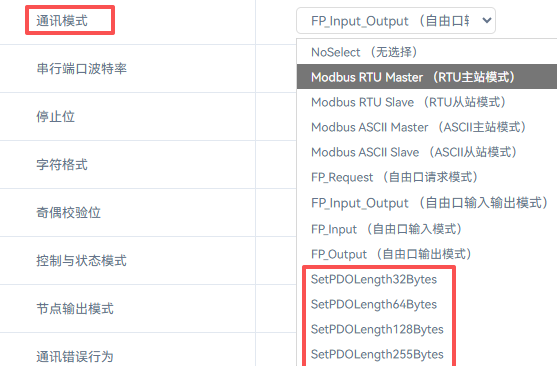
2. Communication Mode Selection
The Modbus mode is divided into 4 types, as shown in the table below:

The RTU and ASCII modes have no essential functional difference, differing only in the message encoding format (hexadecimal or ASCII characters). When the module acts as a master station, it is typically used to connect to slave devices such as instruments; when acting as a slave station, it is used for data exchange with an upper computer or other master stations.
3. Control Mode
The control mode is divided into 3 types:
Disable: Control and status are disabled. The module defaults to sending the set message upon power-up.
Level: Control and status are enabled - high-level trigger. Messages are sent in a polling manner.
Rising Edge: Control and status are enabled - rising edge trigger. A message is sent only once when enabled.
Note: In both Level and Rising Edge modes, the module requires configuration of a control word for operation.
4. Error Handling Settings
During serial communication, timeouts, parity errors, length mismatch warnings, etc., may occur. This setting configures whether to retain the current data when such warnings/alarms are triggered.
5. Time Parameter Configuration
Respond Timeout: The time the module waits for a response from the slave station after sending a request.
Poll Delay: The time interval between the module completing the last action and initiating the next poll.
Slave Respond Delay: The response return time set when the module acts as a Modbus slave station (not applicable in Freeport mode).
6. Frame Interval Setting
The frame interval refers to the time gap with no data transmission between two consecutive valid data frames in serial communication. The default is 1.5 character times (1.5T) and can be increased based on the actual message frame in use.
7. Master Station Node Configuration
This section contains the most critical configuration for the module. A complete configuration example follows:
Master read request 1: 01 03 10 00 00 02 C0 CB
Slave read response 1: 01 03 04 12 34 56 78 81 07
Master write request 2: 02 10 20 00 00 02 04 0A 0B 0C 0D D3 F5
Slave write response 2: 02 10 20 00 00 00 02 4A 3B
Based on the messages, the module needs to perform the following operations:
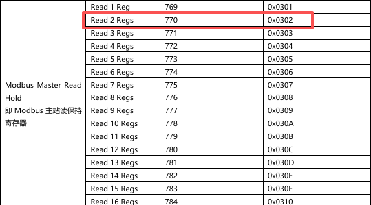
Read 2 registers of data starting from Modbus address 1000 of station 01 using function code 03.
Write 2 registers of data (
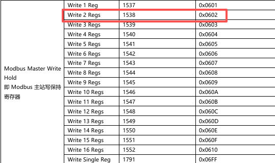
0A 0B 0C 0D) starting from Modbus address 2000 of station 02 using function code 16 (0x10).
When configuring nodes, only the following parameters need to be set: Station Number, Function Code, Start Address, Number of Registers. The read and written data are stored in the process data area (i.e., RX/TX addresses).
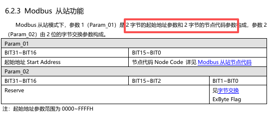
The parameter configuration for Modbus RTU master nodes with a control word is as follows:
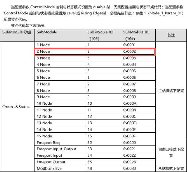
Node1 Param1 -- Decimal: 2 (Hex: 0x02)
Node1 Param2 -- Decimal: 0 (Hex: 0x00)
Node2 Param1 -- Decimal: 268436226 (Hex: 0x10000302)
Node2 Param2 -- Decimal: 1 (Hex: 0x01)
Node3 Param1 -- Decimal: 536872450 (Hex: 0x20000602)
Node3 Param2 -- Decimal: 2 (Hex: 0x02)
Note: In the hexadecimal node parameters, the first 2 bytes represent the start address, and the last 2 bytes are filled in according to the manual specifications.
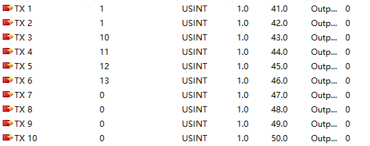
8. Master Module Application Example
The data arrangement with a control word is shown below:
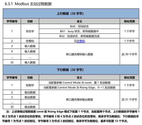

Configure the process data in the PLC data interface as follows:
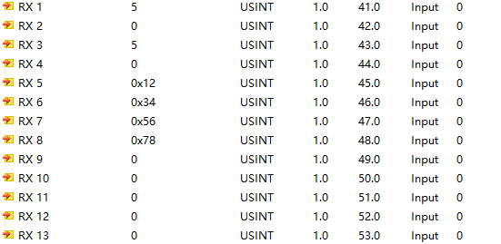
The Modbus slave data exchange interface displays as follows:
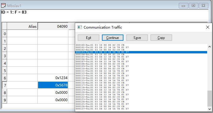
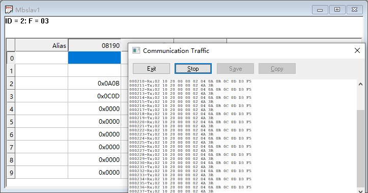
It can be seen that when the module acts as a master station communicating with a Modbus slave, the read and write functions operate normally.
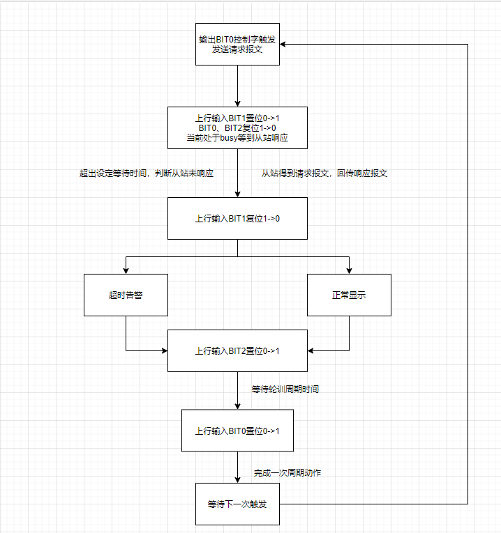
9. Module Single-Cycle Timing Diagram
10. Module Byte Count Switching Instructions
The same XB6S-C01SP module is available in 4 different specifications, with 32 bytes as the default. A 32-byte module can be configured for a maximum of 32 bytes input and 32 bytes output each (excluding the control word). If a control word is configured, causing the process data to exceed 32 bytes, it is necessary to switch to a 64-byte module.
The switching method is similar across different protocols. Based on normal communication with a 32-byte module, the required byte count is issued by the coupler via the communication mode parameter.
After issuing the command, power cycle the coupler. The switch is then complete. In the configuration software, replace the 32-byte module with the corresponding byte count module.
The above is the configuration introduction for the Solidot Remote I/O Serial Communication Module XB6S-C01SP in Modbus communication. Thank you for reading.