Quick Start Guide for Solidot's Modbus TCP All-in-One Module
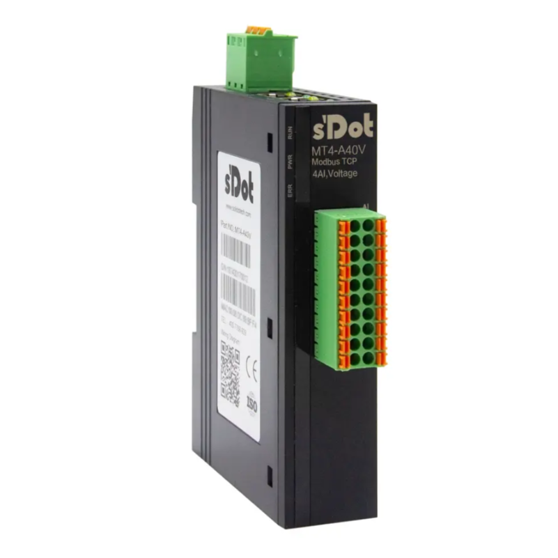
The MT4 series is a Modbus TCP protocol all-in-one I/O module launched by Solidot. It features dual industrial Ethernet ports, a built-in switch, and a compact structure. This series offers a comprehensive range of module types, including digital and analog I/O, supporting flexible configuration. To address common configuration and operational issues encountered by users in practical applications, this article provides a concise guide to key parameter settings and functional applications.
I. Parameter Configuration & IP Address Change
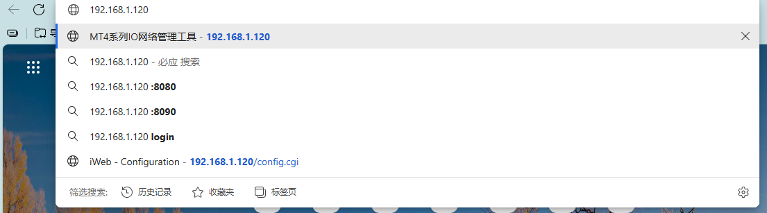
First, locate the corresponding module and wire it correctly according to the diagrams in the wiring chapter of the MT4 Series All-in-One I/O User Manual. After powering on and connecting the module to your computer via an Ethernet cable, enter the module's default IP address, 192.168.1.120, into your browser to access the configuration interface, as shown below:
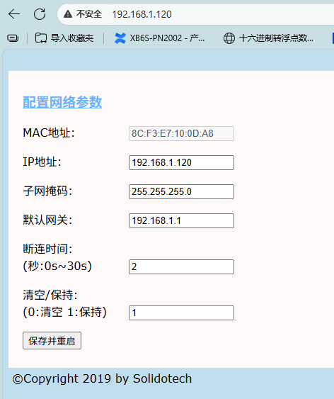
The image below shows the configurable parameters supported by the MT4 series. Among them——
"Disconnect Time" refers to the period after the master station stops sending packets before the module determines the connection is lost. Setting this to 0 disables this function.
"Clear/Hold" determines whether outputs are cleared or held when communication between the module and the master station is interrupted.
After modifying the configuration parameters, click "Save and Reboot" below. Wait for the module to restart automatically for the changes to take effect.
II. Module Usage
1. Digital I/O Usage
Refer to the table below for the digital I/O function addresses:
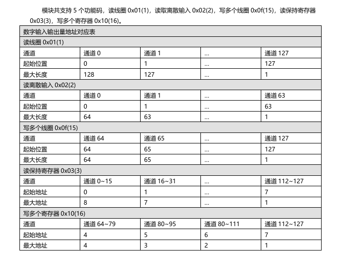
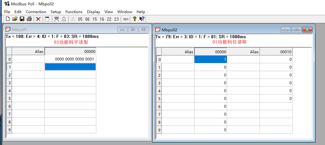
Inputs can be read using Function Codes 01, 02 (bit read), or 03 (word read), as shown below:
Outputs can be written to using Function Codes 15 (bit write) or 16 (word write), as shown below:
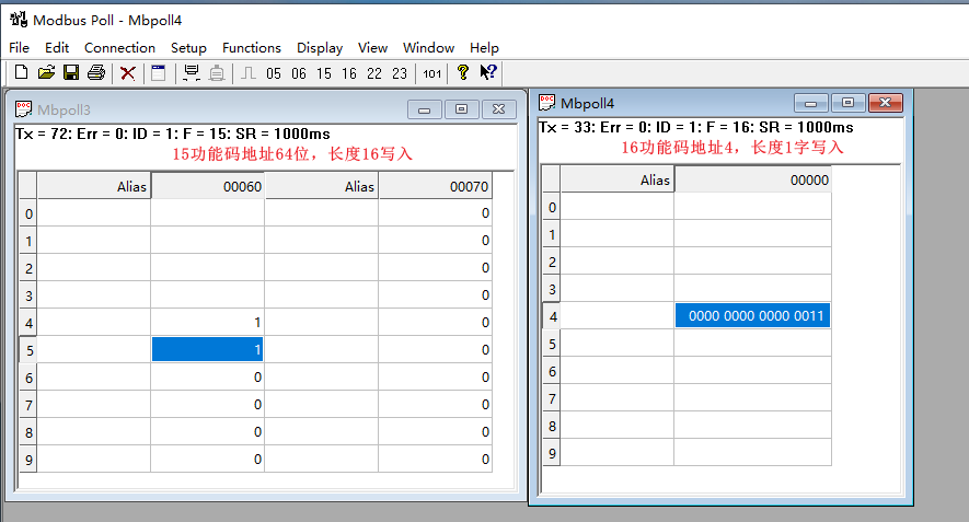
Note: Only one function code can be used for writing operations at a time.
2. Analog I/O Usage
(1) Reading and Writing Channels
Refer to the table below for the analog I/O function addresses:
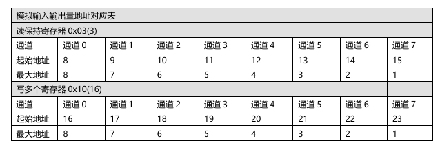
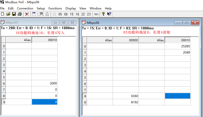
Inputs can be read using Function Code 03, and outputs can be written to using Function Code 16, as shown below:
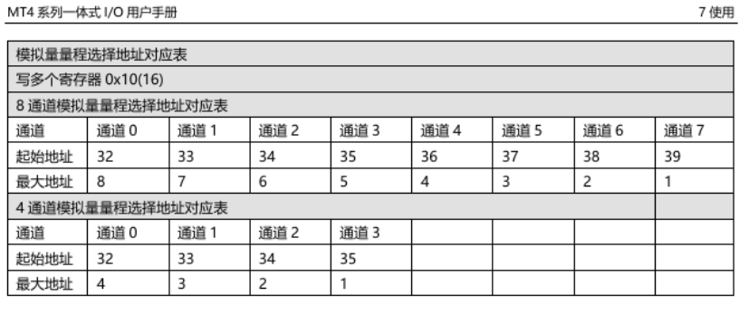
(2) Changing Analog Range
Changing the analog range requires writing values to the corresponding address for each channel. The address for each channel is shown in the table below:
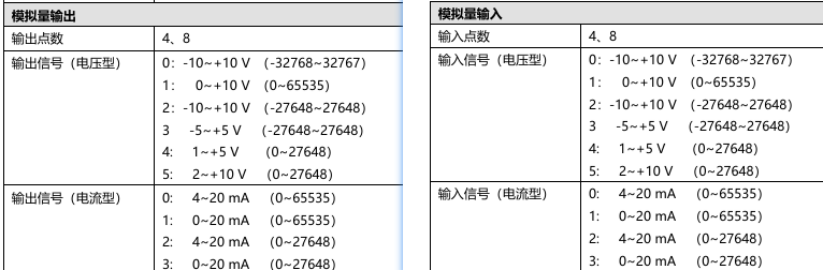
The configurable ranges are shown in the image below. Since this involves register changes, the values need to be rewritten after each power cycle of the module.
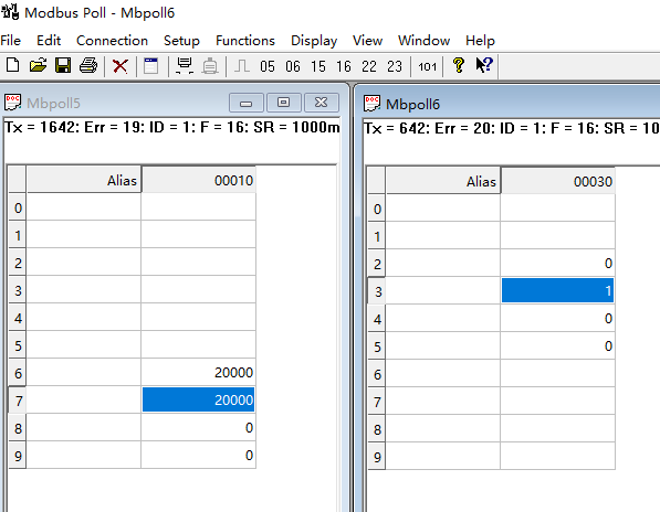
Taking the MT4-A04V four-channel voltage output module as an example——
While assigning an output code value of 20000 simultaneously:
For Channel 1 with Range set to 0:
-10V10V (-3276732767), the output voltage is 6.11V.
For Channel 2 with Range set to 1:
010V (065535), the output voltage is 3.06V.
Configuration is successful once set up as shown in the image below.
This concludes the Quick Start Guide for Solidot's Modbus TCP protocol all-in-one I/O modules. Thank you for reading.