Solidot Remote I/O XB6S Serial Communication Module Freeport Configuration Method Introduction
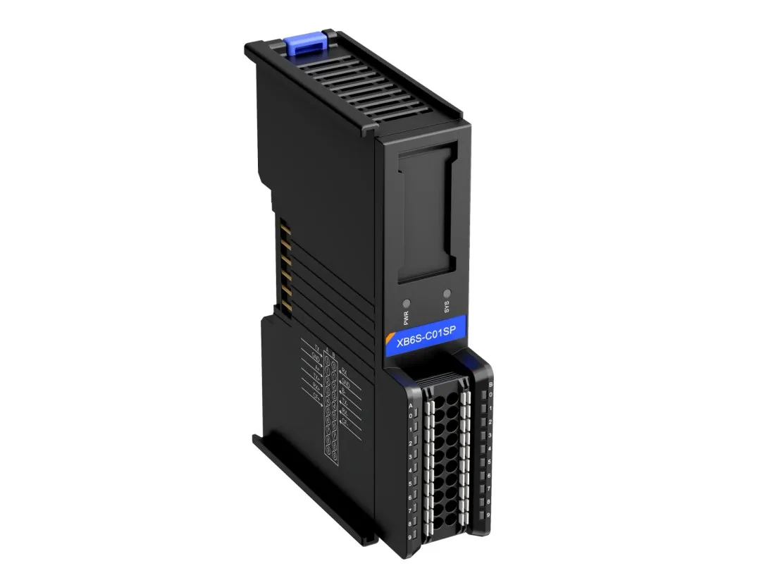
The XB6S-C01SP is a 1-channel serial communication module in the XB6S series, compatible with XB6S series couplers. The module features a compact footprint and simple data exchange processing, capable of meeting serial communication requirements for various application scenarios. This article introduces the Freeport configuration method for the XB6S-C01SP, with specific steps as follows:
I. Serial Port Parameters
Parameters must be configured for connecting physical serial cables (including 232/485/422), including baud rate, stop bits, character format, parity bit, etc.
II. Mode Selection
The Freeport mode is divided into four types: FP_Request (Freeport Request Mode), FP_Input_Output (Freeport Input-Output Mode), FP_Input (Freeport Input Mode), and FP_Output (Freeport Output Mode).
【FP_Input】Usage Scenario: The module only receives data sent from an external serial port. Commonly used for barcode scanners, NFC data reading, etc.
【FP_Output】Usage Scenario: The module only sends data out via the serial port. Commonly used for status indicator lights, alarms, etc.
【FP_Request and FP_Input_Output】Both are modes that involve both sending and receiving. The difference between them is that FP_Request is primarily sequential; it can set a wait time to determine if the slave station has timed out, generating an alarm signal. FP_Input_Output is non-sequential, where sending and receiving have no direct relationship. Operations like timed polling sends or sending once and receiving multiple times are possible.
III. Control Mode
The control mode is divided into three types: Disable (Control and Status disabled), Level (Control and Status enabled - high-level trigger), and Rising Edge (Control and Status enabled - rising edge trigger).
In Disable mode, the module sends the set message by default upon power-up and does not support sending variable-length messages (the sent message must exactly match the configured length). In both Level and Rising Edge modes, the module requires configuration of the control word. Level is for polling message configuration, while Rising Edge sends once when the trigger is enabled.
IV. Error Behavior
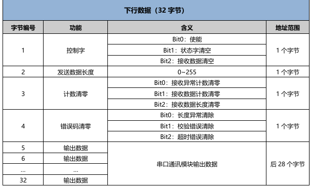
During serial communication, timeouts, parity errors, length mismatch alarms, etc., may occur. This setting determines whether to retain the data when such an alarm is triggered. In configurations for reading variable-length Freeport data, this setting is typically set to Hold.
V. Time Parameters
【Respond Timeout】The response time is the time the module waits for a response from the slave station after making a request.
【Poll Delay】The polling delay is the time between the module completing the previous action and the next poll.
【Slave Respond Delay】The slave response delay is the set return time when the module acts as a Modbus slave (not used in Freeport configuration).
VI. Frame Interval
The frame interval refers to the time gap without data transmission between two consecutive valid data frames in serial communication. The default is 1.5T and can be increased based on the actual message frame usage.
VII. Node Configuration
This section contains the most critical configuration for the module and will illustrate a complete configuration with an example.
Example:
Module request: weight
Device reply: weight xxxxg
Based on the message above, the output message length is 6 bytes, and the return message length is 12 bytes. (In actual configuration, a longer length than the used byte length can be set). Based on the length, the output can be set to 16 bytes and the input to 16 bytes to encompass the above messages.
According to the relevant manual introduction:

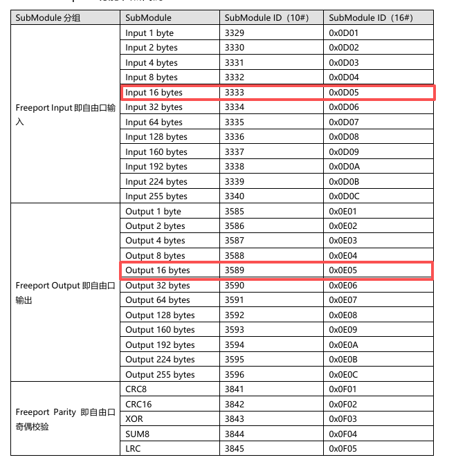
The node parameter configuration with the control word for FP_Request is as follows —
【Node1 Param1】 10#32 (16#20)
【Node1 Param2】 10#0 (16#0)
【Node2 Param1】 10#3333 (16#D05)
【Node2 Param2】 10#0 (16#0)
【Node3 Param1】 10#3589 (16#E05)
【Node3 Param2】 10#0 (16#0)
Node1 Param1 is for the control word usage. Since this example uses FP_Request mode, the control word for FP_Request is 10#32 (16#20). Node2 Param1 sets the input length to 16 bytes 10#3333 (16#D05). Node3 Param1 sets the output length to 16 bytes 10#3589 (16#E05). All Param2 values are invalid in Freeport mode and can be set to 0.
Note: This example sets 16 bytes. If 16 bytes are insufficient during customer use, it can be changed to other byte counts. Or, configure an additional input or output in the next node. If Node4 Param1 is set to — 10#3332 (16#D04), the total input becomes 16 + 8 = 24 bytes.
VIII. Module Application Example
Output data is filled according to the manual definitions, converting ASCII to hexadecimal for transmission:
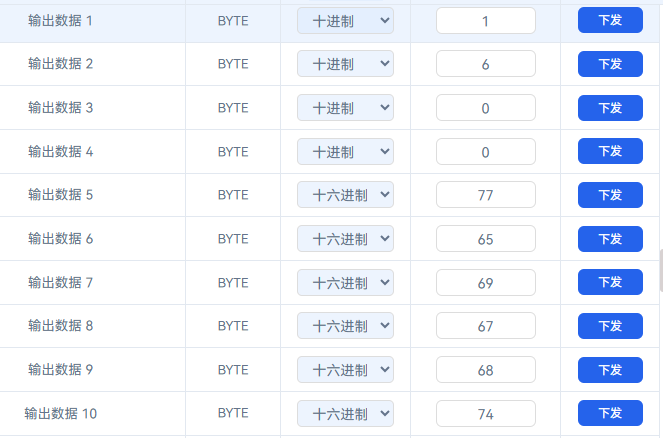
The process data above indicates sending 6 bytes of ASCII data (weight). Using a parallel serial port assistant, it can be captured that the device returned (weight 1354g).

In the input data, according to the manual definitions, the module read 12 bytes, corresponding to the data.


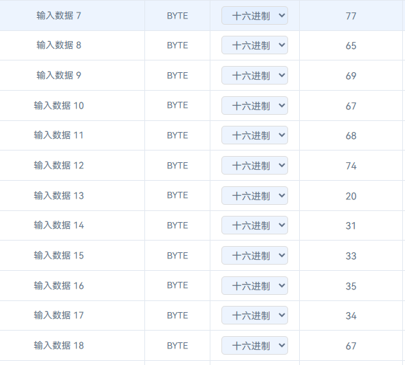
Verification through a third-party conversion shows the hexadecimal read value is correct, completing a normal data exchange.

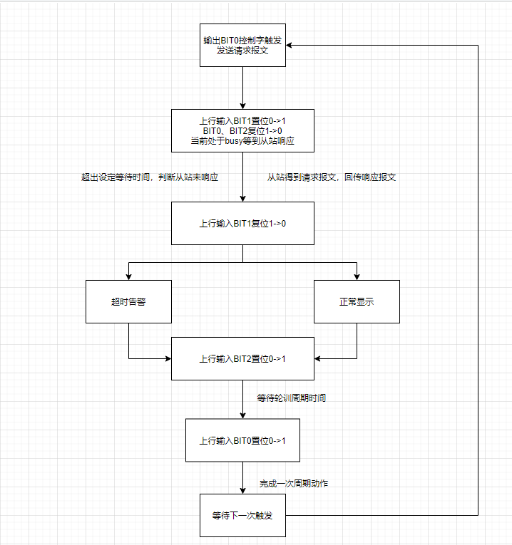
IX. Module Single Cycle Timing
X. Changing Module Byte Count
The same XB6S-C01SP module comes in 4 different specifications. The default module is 32 bytes. A 32-byte module can be configured for a maximum of 32 bytes input and 32 bytes output each (excluding the control word). If the control word is configured, the process data might exceed 32 bytes, requiring a switch to a 64-byte module.
The switching method is roughly similar for different protocols. Based on normal communication with the 32-byte module, issue the required byte count switch command in the communication mode parameters of the coupler.

After issuing the command, power cycle the coupler. The switch is then complete. Replace the 32-byte module in the configuration with the module of the corresponding byte count.
The above is the introduction to the Freeport configuration method for the Solidot Remote I/O XB6S serial communication module.