Troubleshooting and Resolution Guide for Solidot Discrete I/O XBF4-PN04 Communication Issues
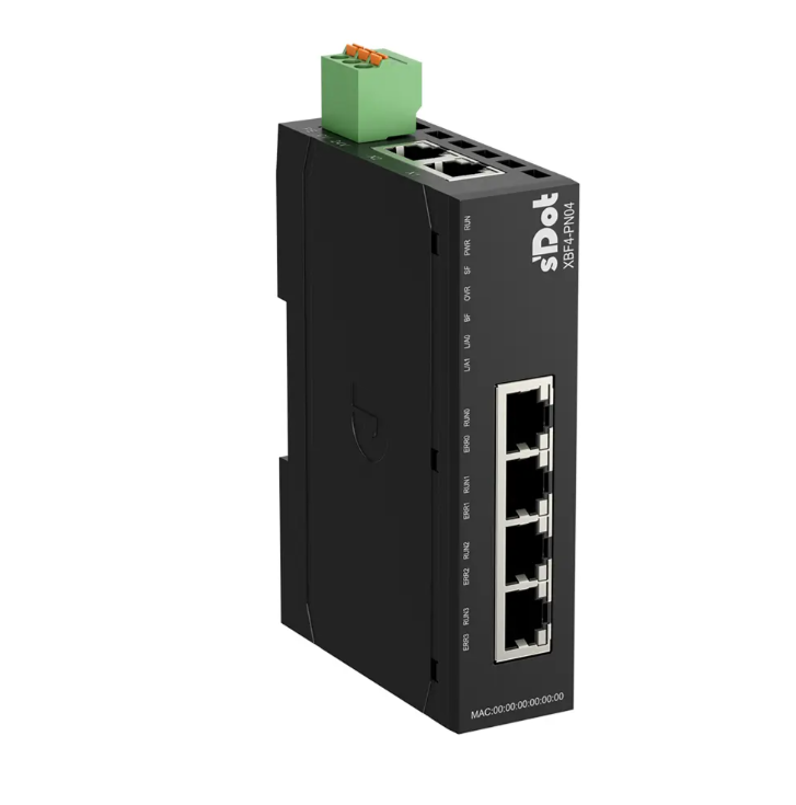
The XBF4-PN04 is a PROFINET bus coupler module belonging to Solidot's discrete I/O series. It features two RJ45 PROFINET ports on its top for communication with a PROFINET master PLC. On the front, there are four RJ45 XBF expansion ports, allowing for serial connection of various types of discrete I/O modules. Each port can connect up to 16 modules in series (modules have address switch settings from 0 to F, which must be unique), enabling a maximum expansion of 32 discrete I/O modules in total.
During the use of the XBF4-PN04, users may encounter issues where normal communication with the PROFINET master cannot be established during configuration or operation. This guide systematically explains how to quickly locate and resolve such communication problems by observing indicator light statuses and performing step-by-step troubleshooting.
Part 1: Preparation - Identifying Indicator Light Statuses
Before troubleshooting, it is essential to understand the definitions of the indicator lights on both the coupler and the I/O modules to quickly pinpoint issues based on their statuses.
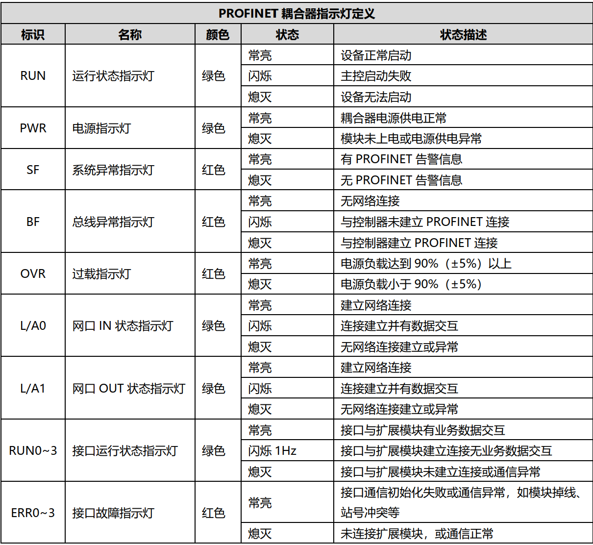
Coupler Indicator Light Definitions: (Image/Description Placeholder)
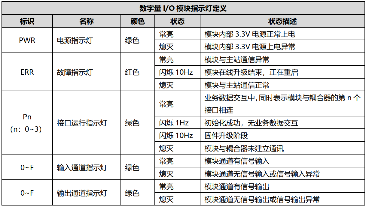
I/O Module Indicator Light Definitions: (Image/Description Placeholder)
Part 2: Problem Symptoms and Resolution Steps
1. PROFINET Communication Protocol Layer - Physical Network Link Disconnected
Module Symptom: The L/A0 and L/A1 lights on the XBF4 coupler are both off.
Solution:
① Check if the network cable between the coupler and the master station is normal and the connection is secure (it is recommended to use a certified Cat5e or better pre-made network cable).
② Check if the PLC's Ethernet port is functioning correctly and if the correct port is being used.
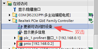
③ Check if the PLC software can discover the coupler.
2. XBF Bus Layer - Physical Network Link Disconnected
Module Symptom:
① The RUN n (n: 03) lights on the XBF4 coupler are off, and the EER n (n: 03) lights are off.
② The PWR, ERR, and Pn (n: 0~3) lights on the I/O modules are off.
Solution:
① Check if the network cables between the I/O modules and the coupler are normal and the connections are secure (use Cat5e or better cables).
② Check the pinout sequence of the RJ45 connectors on both ends of custom-made or pre-made network cables. Use straight-through cables; crossover cables are not needed.
3. Terminating Resistor Not Installed
Module Symptom: The Pn (n: 0~3) lights on the I/O modules are flashing or off.
Solution:
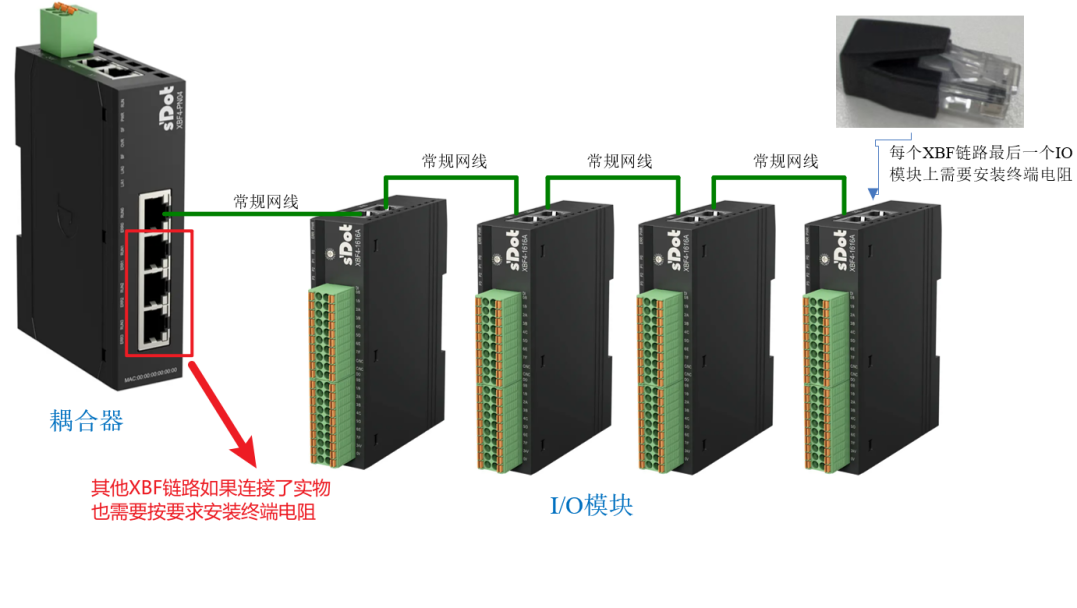
① Check if a terminating resistor is installed on the last I/O module of the used XBF link (by default, the factory installs it on the coupler), as shown in the first XBF link installation example in the image below.
② For C3 valve terminals, an additional accessory is required for the terminating resistor.
4. I/O Module Address Switch Conflict
Module Symptom:
① The RUN n (n: 03) lights on the XBF4 coupler are off, and the EER n (n: 03) lights are solidly lit.
② The PWR light on the I/O modules is solidly lit, while the ERR and Pn (n: 0~3) lights are off.
Solution: Check for any address switch conflicts among I/O modules on the same XBF link.
5. Mismatch Between Configured I/O Module Types/Slot Order and Physical Setup, or Unconfigured Modules
Module Symptom:
① The RUN n (n: 03) lights on the XBF4 coupler are flashing, and the EER n (n: 03) lights are off.
② The PWR light on the I/O modules is solidly lit, the ERR light is off, and the Pn (n: 0~3) lights are flashing.
Solution:
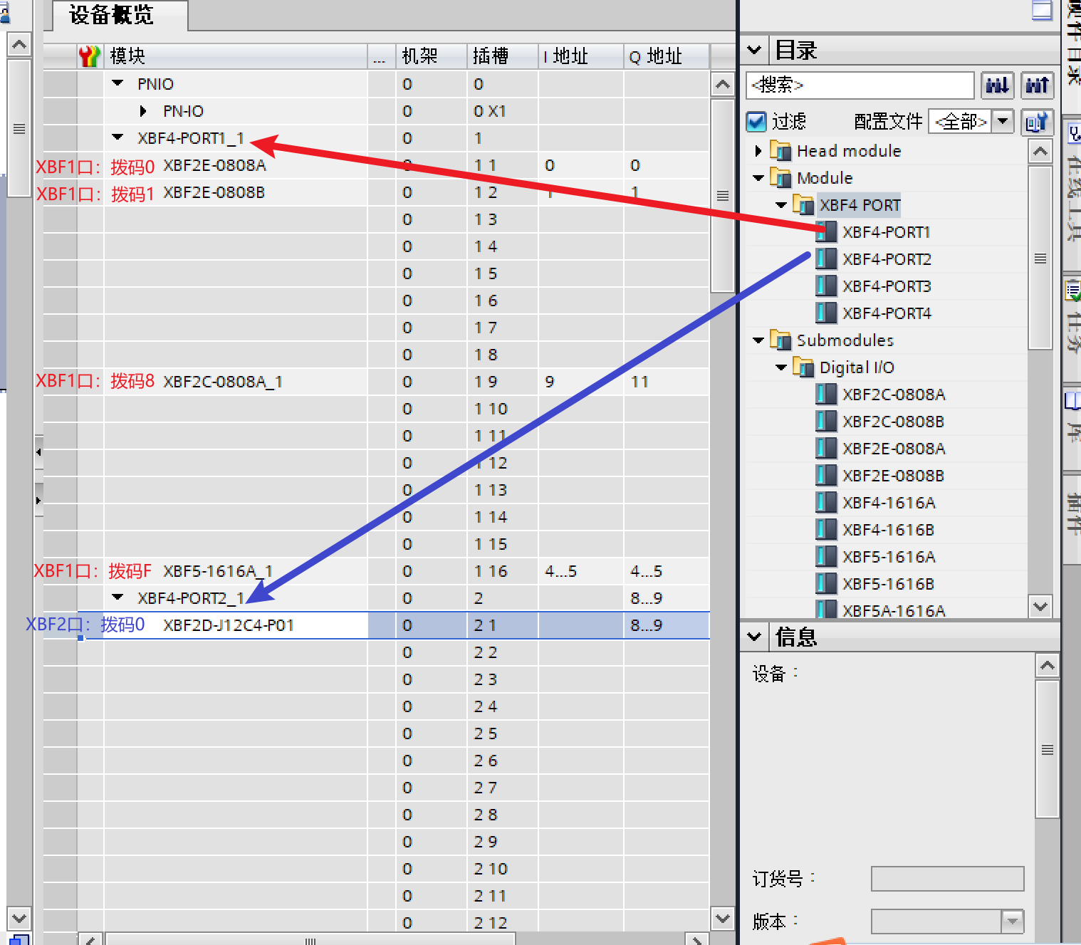
① Check if the configured PORT number matches the physical PORT connection on the coupler. PORT1-4 correspond to the coupler's four ports respectively.
② Check if the configured slot order and module types under each PORT match the physical address switch settings and module models.
6. Coupler Device Name Mismatch or IP Address Conflict
Module Symptom:
① The RUN n (n: 03) lights on the XBF4 coupler are flashing, the EER n (n: 03) lights are off, the BF light is flashing, and the RUN and PWR lights are solidly lit.
② The PWR light on the I/O modules is solidly lit, the ERR light is off, and the Pn (n: 0~3) lights are flashing.
Solution:
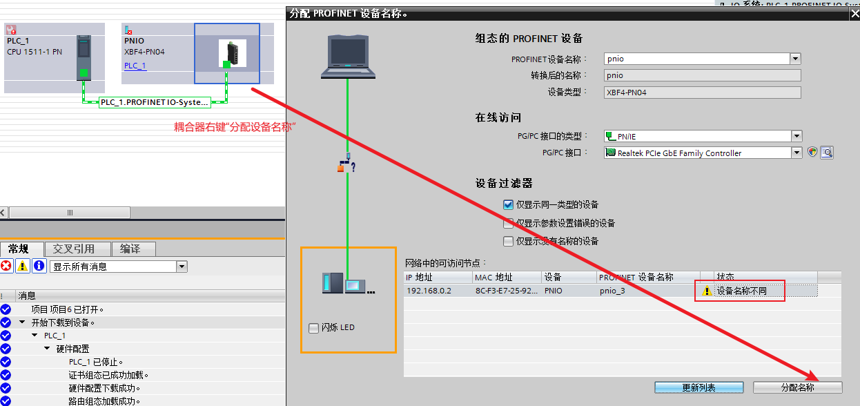
① Correctly assign the device name, download the hardware configuration, and then power cycle the PLC.
② Check if the coupler's IP address conflicts with other devices on the network.

7. Incorrect Operation Sequence: Coupler Powered On Before Connecting I/O Module Cables and Setting Addresses
Module Symptom:
① The RUN n (n: 03) and EER n (n: 03) lights on the XBF4 coupler are off.
② The PWR light on the I/O modules is solidly lit, while the ERR and Pn (n: 0~3) lights are off.
Solution:
① Follow the correct sequence: Ensure the XBF4 coupler is powered OFF. First, complete the I/O module address setting, install the terminating resistor on the last module of each XBF link, and connect the I/O module network cables to the XBF coupler (these three steps have no priority order). Then, power ON the XBF coupler.
② If the sequence was incorrect, simply power cycle the coupler.
8. Incorrect Power Wiring/Supply
Module Symptom: The PWR light on the XBF4 coupler is not lit.
Solution:
① Wire the module correctly according to the manual and apply normal power. The PWR light should illuminate.
② If the power supply voltage is unstable or ramps up in steps, re-power the module and ensure a stable supply voltage.
9. XBF4 Coupler Malfunction
Module Symptom:
① The PWR light remains off after multiple power cycles, but a multimeter check confirms normal power supply.
② Only the PWR light on the coupler is solidly lit; all other indicators are off.
③ The EER n (n: 0~3) lights remain solidly lit after a power cycle, even with no I/O modules connected.
Solution:
① If the coupler is abnormal, replace the coupler.
② If the coupler is damaged, replace the coupler.
10. I/O Module Malfunction
Module Symptom:
① The I/O module's PWR light remains off after multiple coupler power cycles, even though the power supply is normal and the network cable between the coupler and I/O module is fine.
② Only the PWR light on the I/O module is solidly lit; the ERR and Pn (n: 0~3) lights are off.
Solution:
① If the I/O module is abnormal, replace the I/O module.
② If the I/O module is damaged, replace the I/O module.
11. Master PLC Malfunction
Module Symptom: The PLC cannot switch its current state or frequently reports bus alarms.
Solution:
① Consult the specific PLC model's manual for diagnostics. For detailed current status information, contact the controller manufacturer.
② The PLC resources may be insufficient to handle more modules.
12. Strong Interference Causing Disconnections or Failed Communication
Module Symptom:
① Packet loss occurs on the bus communication.
② The XBF4 coupler shows RUN lights flashing or turning off, indicating communication alarms.
Solution:
① Interference can come from two sources: power signals and communication lines. Identify the interference source and optimize wiring to keep away from sources like high-power inverters, servo motors, and drives.
② Add ferrite cores to network cables to reduce interference.
③ Use shielded network cables whenever possible.
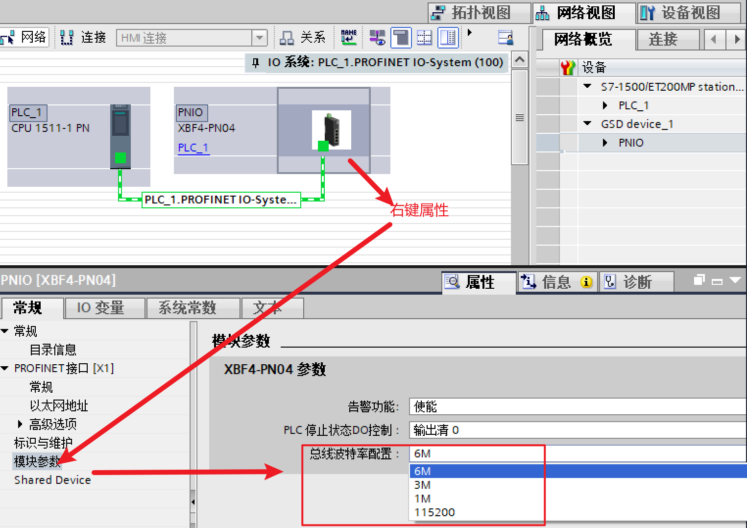
④ Reduce the baud rate on the XBF4 coupler. The default maximum is 6MHz; it can also be set to 3M, 1M, or 115200Hz.
This concludes the troubleshooting and resolution guide for communication issues with the Solidot discrete I/O XBF4-PN04. Thank you for reading.