The usage of Modbus message programming in free port mode for Solidot's remote I/O module XB6S serial communication module
Solidot's XB6S series serial communication module XB6S-C01SP supports three communication interfaces: RS485, RS422, and RS232. It also supports multiple communication modes including Modbus RTU Master/Slave, Modbus ASCII Master/Slave, and Freeport. Compared with conventional Modbus usage, if the number of node parameter configurations is less than actual usage or if you want to replace other brands without making extensive changes to the program, programming is required for message communication. Below, we will explain the usage of editing Modbus messages under Freeport mode.
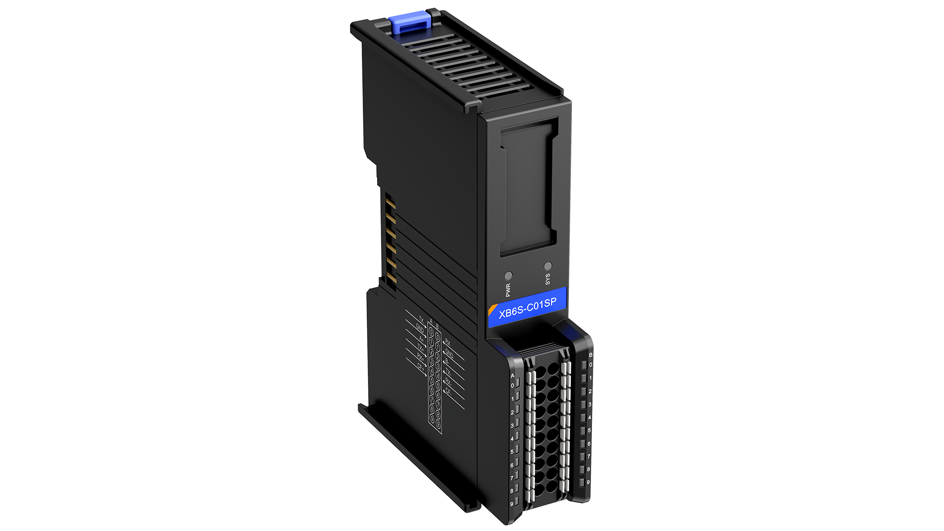
↑ Solidot Serial Communication Module XB6S-C01SP
1. Relationship Between Freeport and Modbus
Essentially, both belong to serial communication, conducting message communication based on serial lines (485/422/232). Modbus has specific format requirements for messages, including a frame structure = Address + Function Code + Data + Checksum. However, Freeport itself has no restrictions, meaning you can write and send messages in a unified format without any specific message formatting requirements. Therefore, to some extent, editing through Freeport, as long as it complies with the Modbus message format, allows communication with devices using Modbus.
2. Parameter Configuration
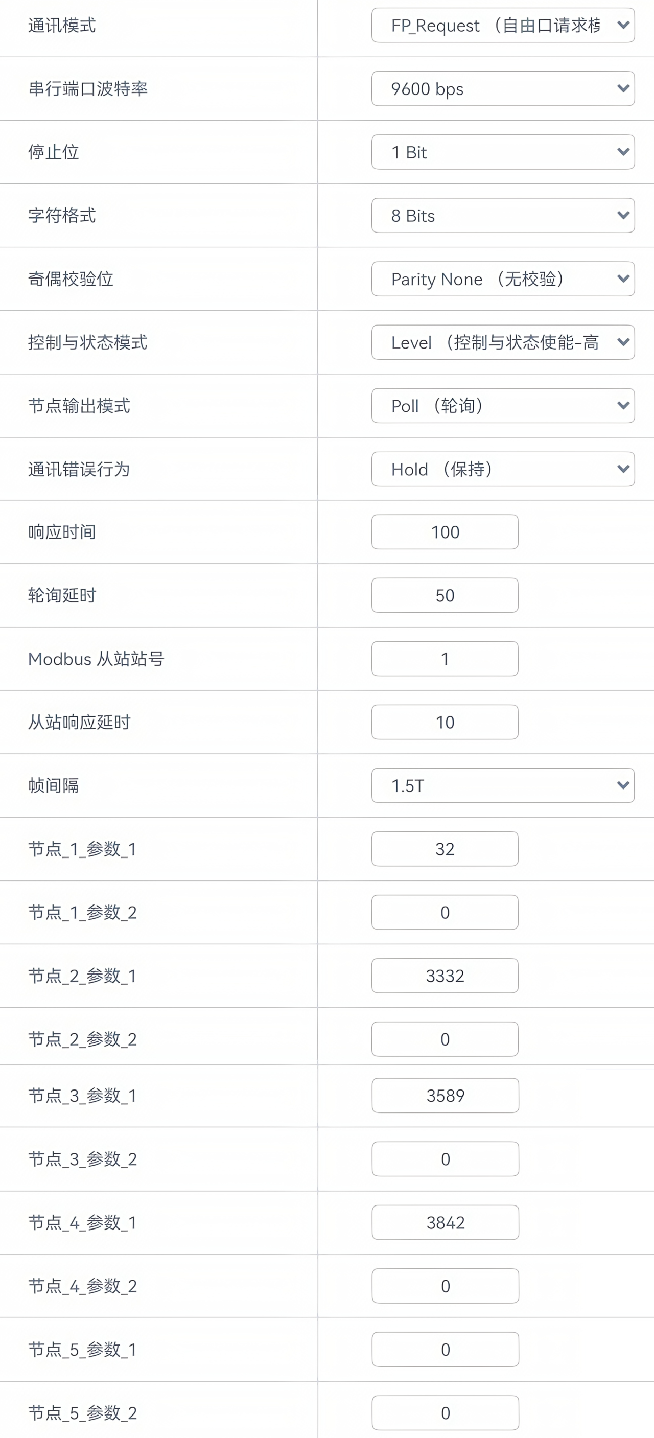
Serial port parameters should remain consistent with the connection. Select Freeport request mode for communication, which includes the request process and waiting delays, while opening control and status modes and changing error behavior to "hold."
According to the manual, the Freeport of the module can be configured: Node 1 Parameter 1 configuration request mode control word 16#20 (10#32), Node 2 Parameter 1 input configuration 16 bytes - 16#D04 (10#3332), Node 3 Parameter 1 output configuration 16 bytes - 16#E04 (10#3589), and add a CRC16 checksum 16#F02 (3842) to the end of the output. This step lays the groundwork for message occupation and adds verification for the message.
3. Process Data
The parameter configuration is complete, and we can now fill in the process data.
Example message: 01 03 00 00 00 02 C4 0B
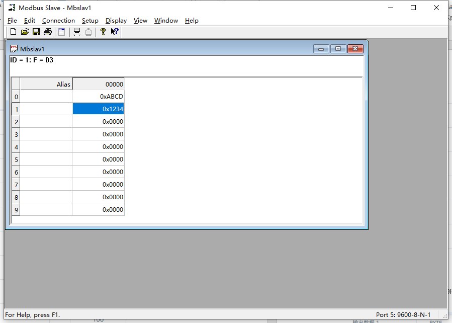
Response: 01 03 04 AB CD 12 34 46 9F
Here, it is hoped that the module will use function code 03 to read the data from the holding registers at the slave address 01, starting from 00 00 for 02 holding registers. This is done by simulating a Modbus slave.
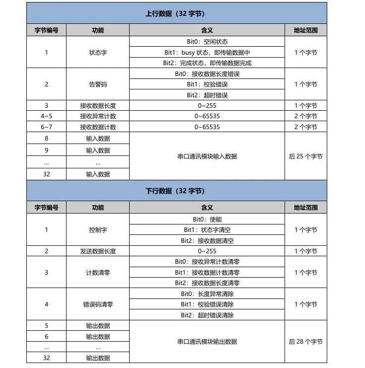
Downlink Data:
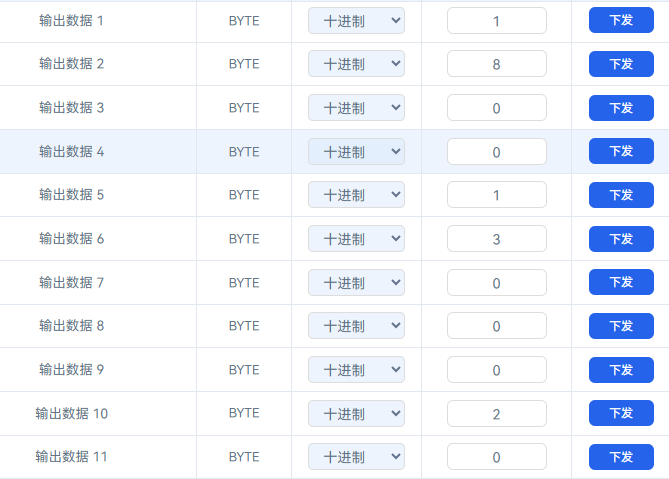
Output Data 1: Control message enable;
Output Data 2: Total byte length of the output message (here, 8 includes the filled message and the automatically added CRC check);
Output Data 3, 4: Exception zeroing action (when the error behavior in the configured parameters is changed to hold, this can default to 0);
Output Data 5: The first data of the sent message.
Uplink Data:

Input Data 1: Status word of the returned message;
Input Data 2: Indicates whether there is an error in the returned message;
Input Data 3: Length of the received message (can be compared with the Modbus standard message for calibration to return whether it is normal);
Input Data 4, 5: Received exception count (this will trigger an alert if the data length does not match completely);
Input Data 6, 7: Received data count (each time data is returned, the count increases by 1, verifying whether it is a new message);
Input Data 8: The first data of the received message.
By truncating the data area, we can see that AB, CD, 12, 34 are the current data in the registers, which means that Modbus communication has been completed on Freeport.
Note: Specific parameter definitions are shown in the figure.
This concludes the usage of editing Modbus messages in Freeport mode for the serial communication module XB6S-C01SP. Thank you for watching!