Solidot Remote I/O Module XB6S: EtherCAT Coupler Alarm Diagnosis and Analysis Methods
The XB6S-EC2002 EtherCAT coupler supports alarm uploading functionality. If a module alarm occurs in the EtherCAT bus, it is immediately reported to the PLC alarm interface, providing real-time I/O module status monitoring and detailed coupler diagnostics.
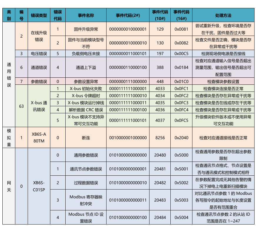
Supported Error Codes:
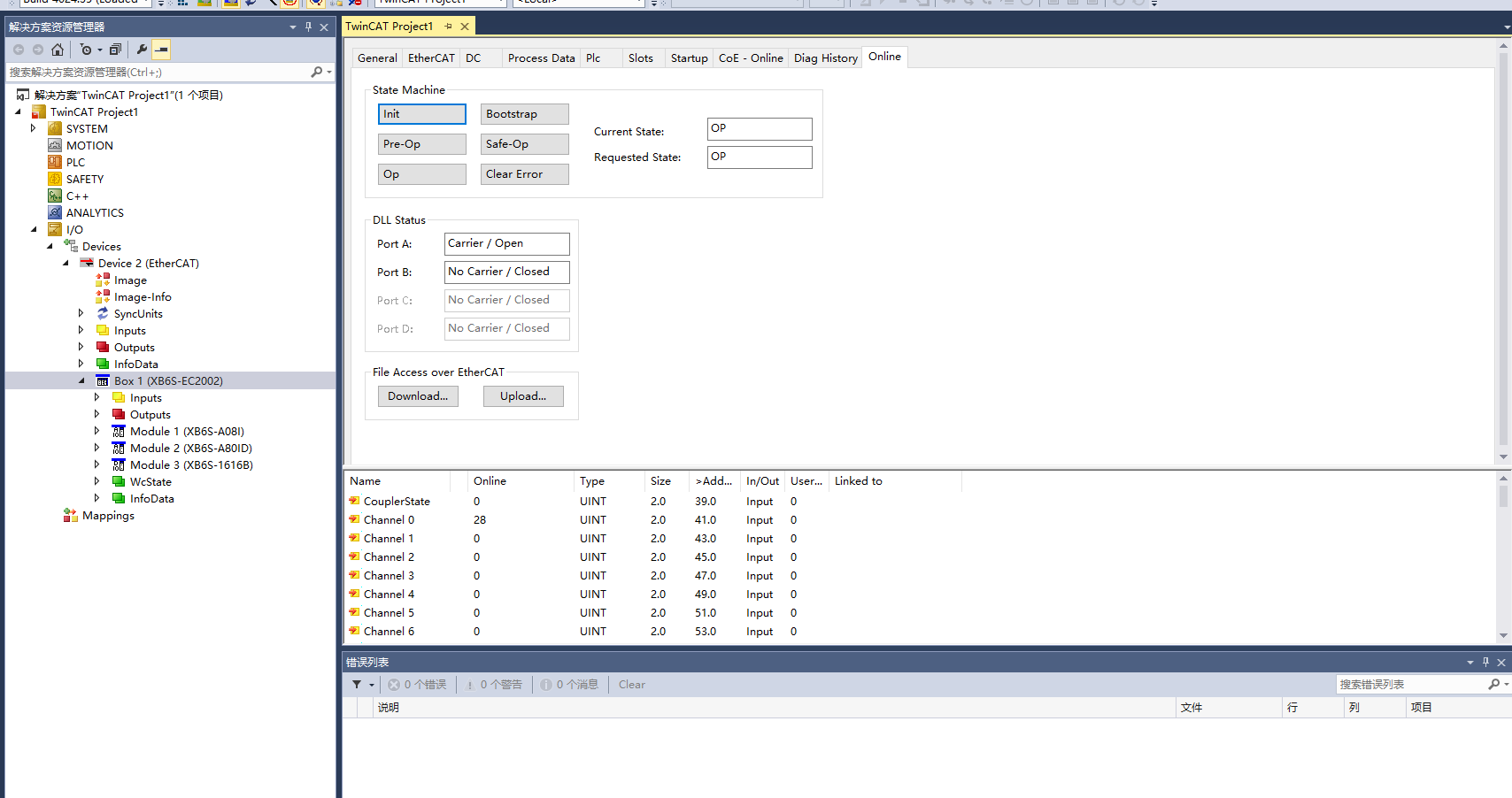
Example using TwinCAT:
When the XB6S-EC2002 is connected to TwinCAT under normal operational status:
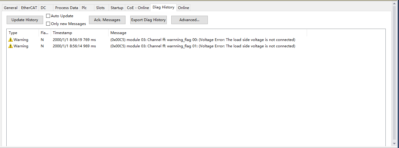
A load-side voltage alarm triggers the following alert:
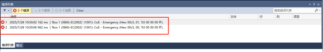
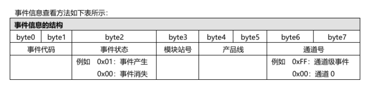
The XB6S-EC2002 manual details byte-specific definitions for such alarms:
Historical alarms can also be queried in the coupler's diagnostic log:
Case Study: Reading Diagnostics via SDO
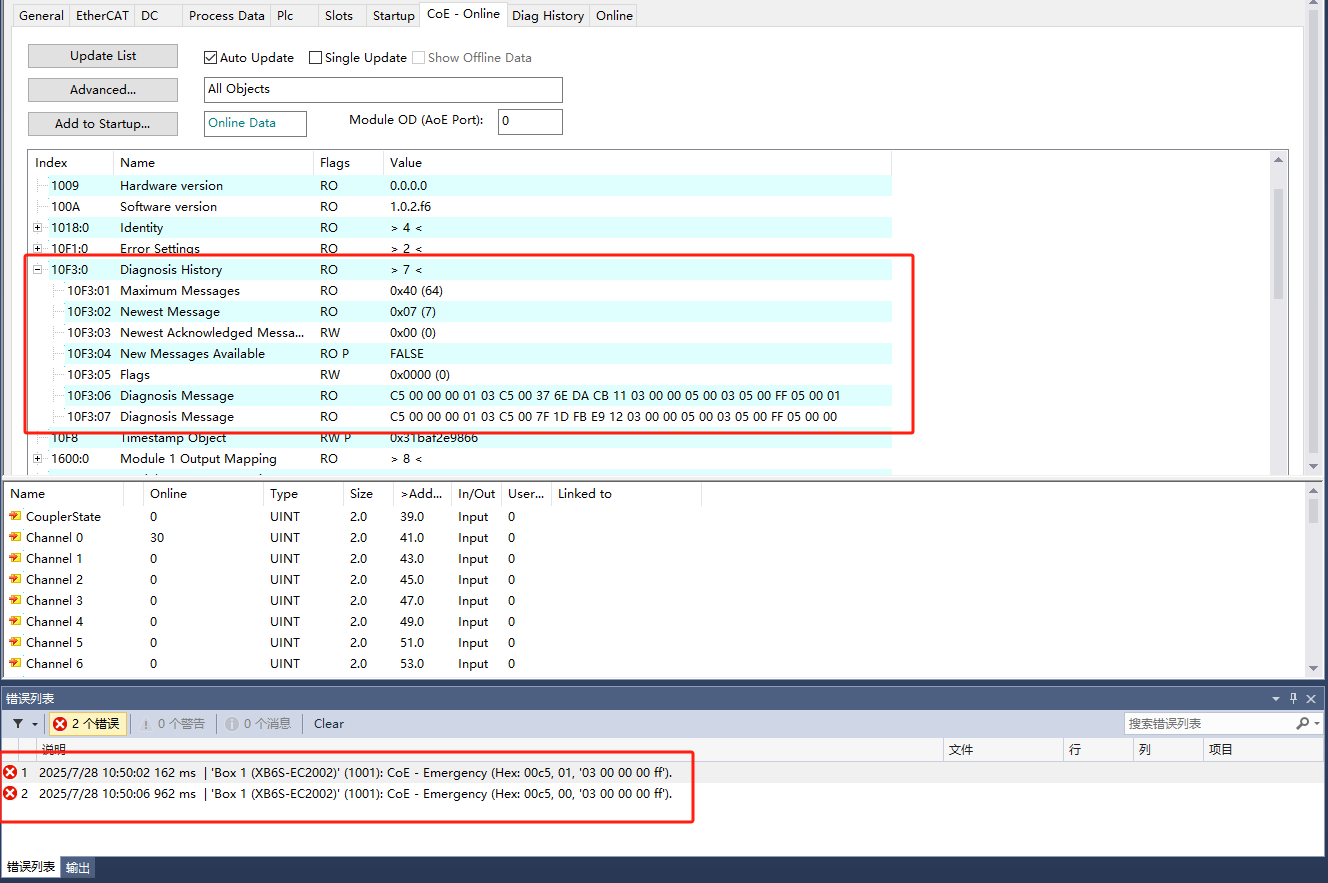
EtherCAT Diagnosis is a channel for slave devices to report errors, with three severity levels: info, warning, and error. Based on CoE protocol, Index=0x10F3:
10F3:01: Max 64 entries10F3:02: Latest message index10F3:03: Acknowledged message ID (write to confirm)10F3:06: Detailed diagnostic message
Sample Message Analysis:C5 00 00 00 01 03 C5 00 37 6E DA CB 11 03 00 00 05 00 03 05 00 FF 05 00 01
C5 00 00 00: Diag code = Load-side power supply failure (per error code table)01 03 C5 00: Module 3 reports load-side voltage alarm (info level)37 6E DA CB 11 03 00 00: Timestamp05 00: Followed by unsigned 8-bit data03: Module 3FF: Channel-level event01: Active alarm (changes to00when resolved)
Reading Index 0x10F3 enables real-time module status analysis.
Critical Notes:
EtherCAT uses a ring-buffer message pool:
Overwrite Mode: New messages overwrite oldest entries when full.
Acknowledge Mode: New messages replace acknowledged ones; unacknowledged messages block new entries.
Mapping alarms to PDOs achieves real-time coupler monitoring.