Configuration method of Solidot IO-Link bus I/O on Omron Sysmac Studio
Article Overview
1. Demo Product
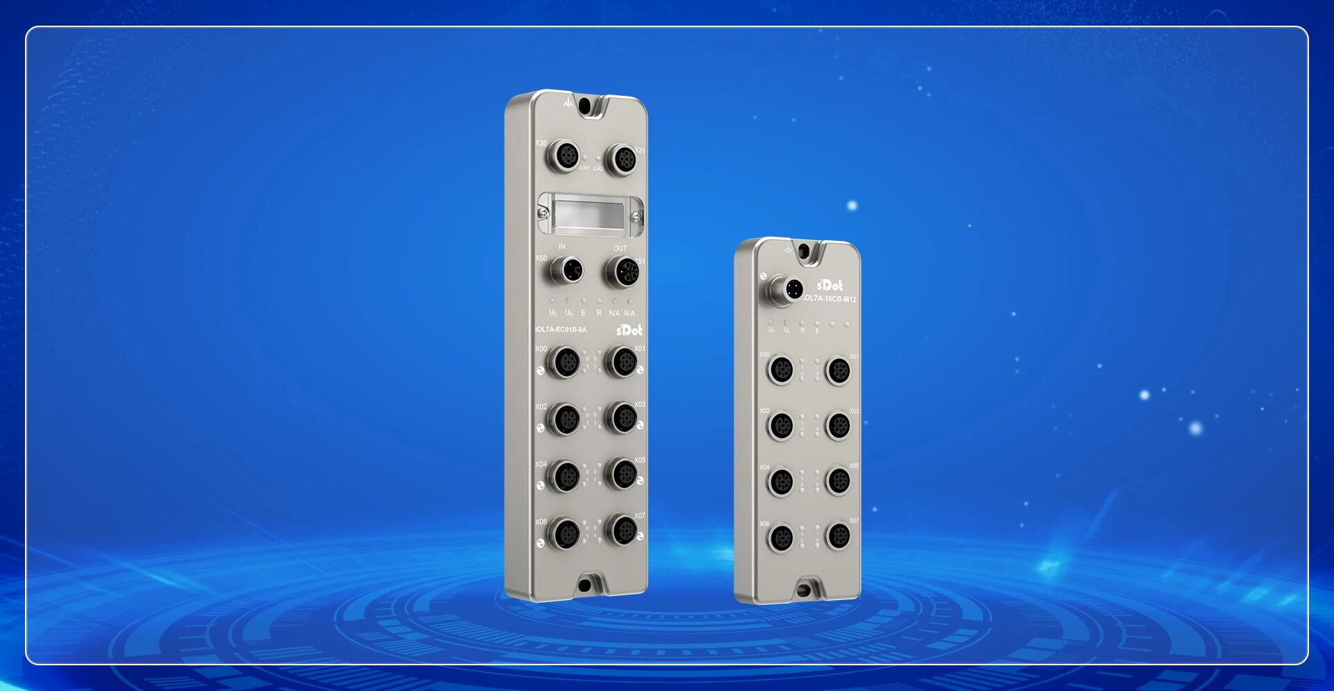
Solidot IOL7A-EC01B-8A 、IOL7A-16CB-M12
2. Communication Protocol
EtherCAT, IO-Link
3. Compatible PLC
Omron NX/NJ Series
4. Configuration Tool
Sysmac Studio
5. Configuration Result
IO-Link bus I/O data mapped to PLC global variables, enabling signal read/write
Solidot IO-Link Hub IOL7A-16CB-M12 can be paired with IO-Link Master IOL7A-EC01B-8A to connect to Omron NX/NJ series PLCs via EtherCAT protocol. This article details the complete configuration process on Sysmac Studio, from XML file installation to variable association.
I. Install XML File
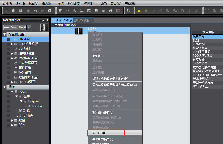
1.Open Sysmac Studio. In the EtherCAT configuration interface, right-click "Master Device" and select "Show ESI Library".
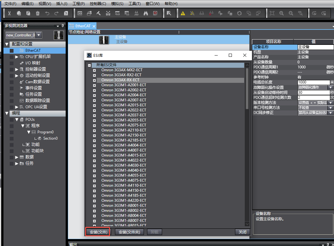
2.In the ESI Library pop-up window, click "Install (File)", select the XML file provided by Solidot. After installation, open it.
II. Online Scan and Write Node Address
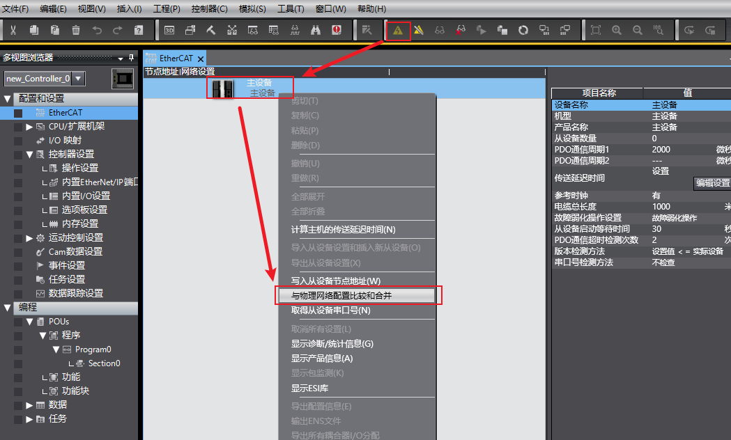
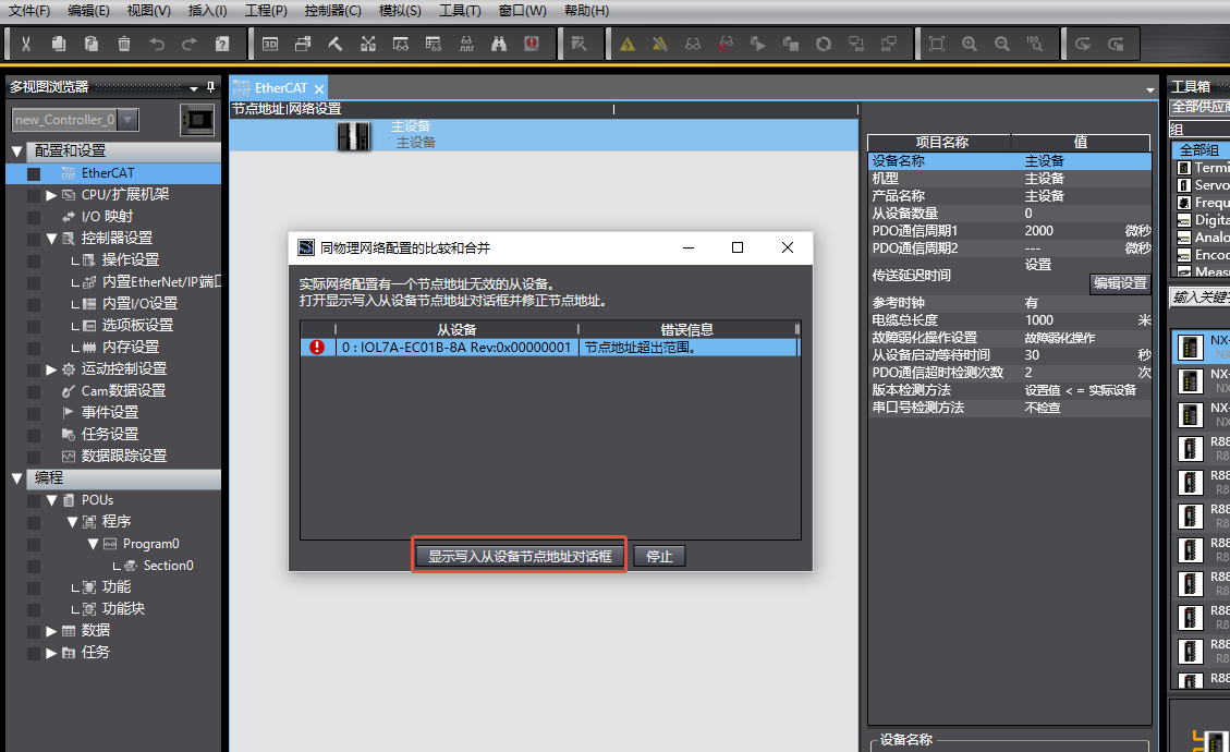
1.After going online with the PLC, right-click "Master Device" and execute "Compare and Merge with Physical Network Configuration".
2.If prompted that the node address is out of range, open "Show Write Slave Node Address Dialog" to correct the node address.
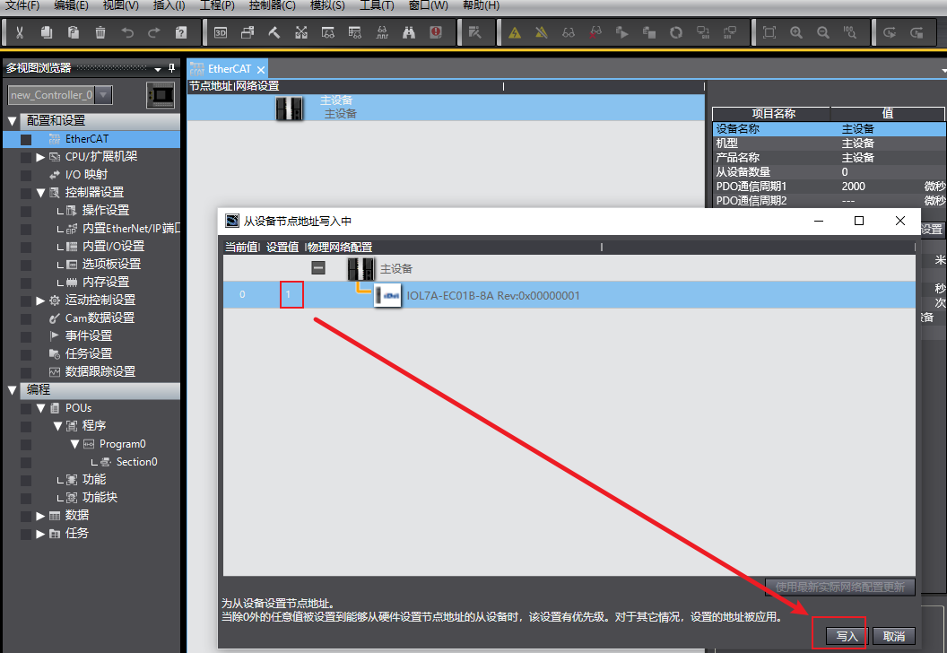
3.Set the node address for IOL7A-EC01B-8A and click "Write". After the write is complete, restart the device power for the setting to take effect.
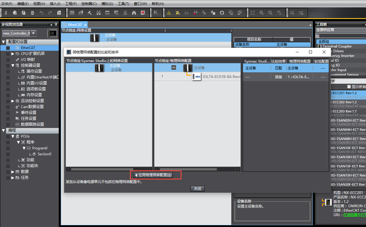
4.Execute "Compare and Merge with Physical Network Configuration" again. In the match interface, select "Apply Physical Network Configuration" to complete device addition.
III. Edit Module Configuration
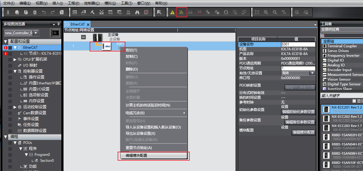
1.Switch the PLC to offline mode. Right-click the newly added master module IOL7A-EC01B-8A and click "Edit Module Configuration".
2.Example configuration: Configure one IOL7A-16CB-M12 on each of master ports X00 and X01 (2 units total). Ports X02 to X07 are unused. In this example, only one IOL7A-16CB-M12 is actually connected to port X00; port X01 is not connected (to demonstrate the status code when disconnected).
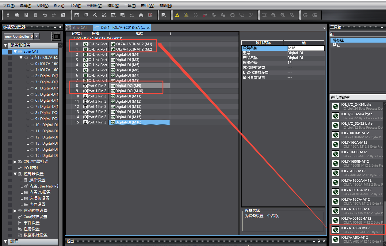
3.Port configuration rules:
• Unused ports must be configured as DI (all ports must be configured; empty slots will prevent program download).
• In this example, PIN2 of Port0 and Port1 needs to be configured as DO, providing power to the UA port of IOL7A-16CB-M12 via the master's PIN2 output function.
4.After configuration, switch the PLC to online mode and download the program to the controller.
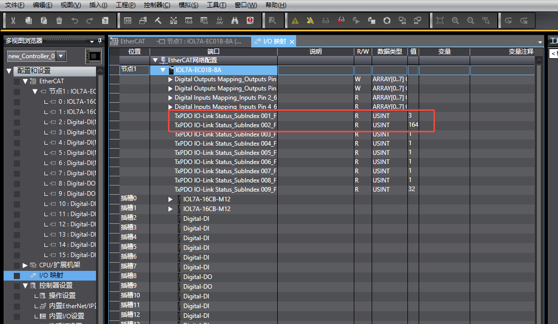
IV. IO-Link Status View and UA Power Activation
1.After program download, view the IO-Link status in the "I/O Mapping" interface (Subindex 001–008). Status code meanings:
• 3: Slave configured and successfully connected
• 164: Slave configured but not connected
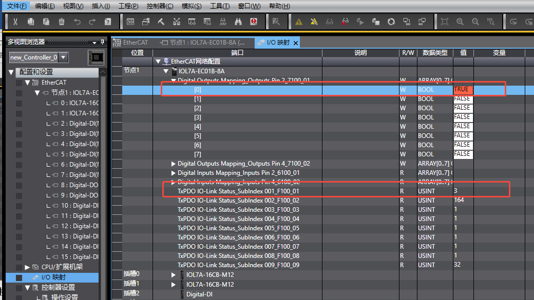
2.If the UA LED of IOL7A-16CB-M12 is flashing, it indicates that the UA port is not powered. In the "Digital Outputs" area of I/O Mapping, set the variable corresponding to Port0/Port1 PIN2 to TRUE to activate UA power.
V. Global Variable Association
Go to the "Global Variables" interface to create variables. The data type can be USINT or 8-bit ARRAY (choose according to programming needs).
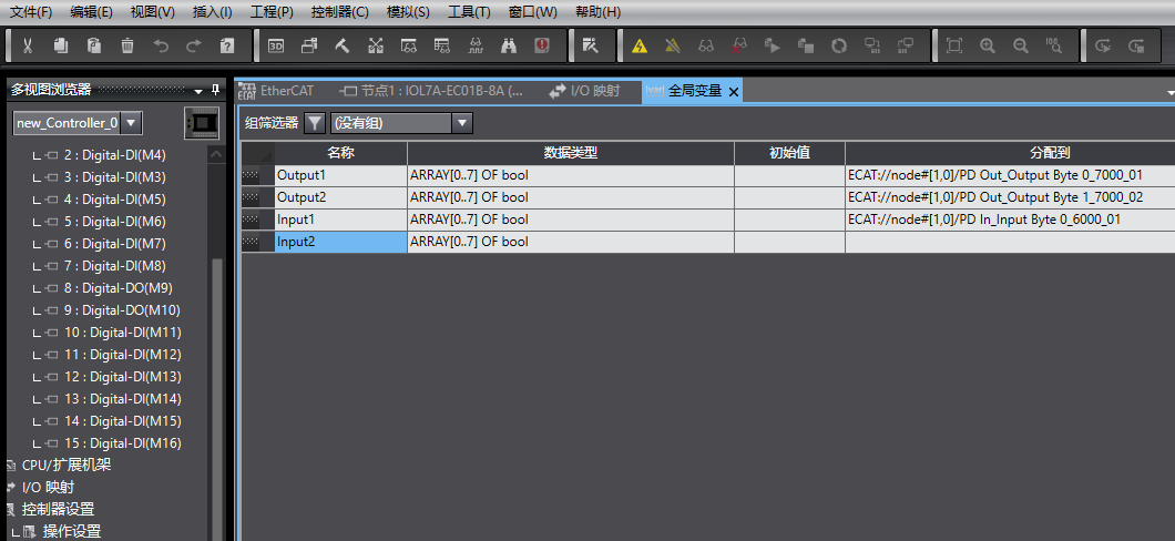
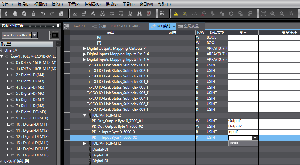
After association, confirm the mapping between variables and ports in the "I/O Mapping" interface to ensure correct mapping.
VI. Module Usage Instructions
IOL7A-16CB-M12is a self-adaptive module; no separate configuration of port input/output direction is required:
• To control slave output, directly assign a value to the associated Output variable.
• When an external signal is input, directly read the input state from the associated Inputs variable.