How to connect serial devices to Modbus TCP? Detailed configuration of XB6S-C01SP free port mode
Article Overview
1. Demo Product
Solidot Modbus TCP Coupler XB6S-MT2002 + Serial Communication Module XB6S-C01SP
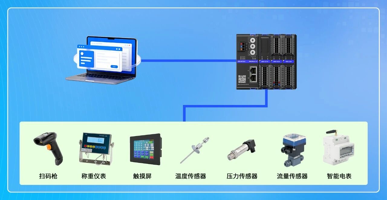
2. Application Scenario
Transparent transmission of RS232/RS422 serial device data to Modbus TCP network via free port mode
3. Configuration Result
Transmit/receive data of serial device is directly mapped to Modbus TCP registers, readable/writable by the host computer
In industrial sites, a common requirement is: you have an RS232 or RS422 serial device (e.g., barcode scanner, sensor, instrument) and want to connect its data to a Modbus TCP network so that the host system can directly read/write it. Solidot's serial communication module XB6S-C01SP offers multiple communication mode options, effectively building a transparent bridge between serial and Modbus TCP.
This article uses the combination of Modbus TCP coupler XB6S-MT2002 + serial communication module XB6S-C01SP as an example to demonstrate the complete process from configuration to verification in free port mode.
I. Hardware Preparation and Wiring
Before starting configuration, confirm correct hardware connections.
Hardware used in this example:
● XB6S-MT2002 (with Web configuration interface)
● XB6S-C01SP (mounted under the coupler)
● USB to RS232 serial cable (to simulate serial device)
● One PC (connected to coupler via Ethernet cable)
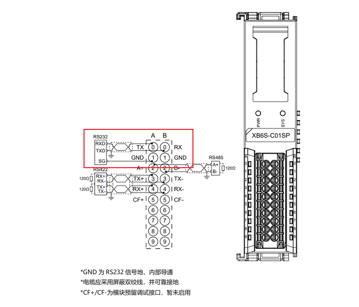
Wiring method:
Connect the PC to the coupler's Ethernet port via a network cable. Connect the USB to RS232 serial cable to the serial terminal of XB6S-C01SP .
Refer to the diagram below for specific wiring.
II. Access Coupler Web Configuration Interface
XB6S-MT2002 supports direct parameter configuration via a browser, no additional software required.
After connecting the PC to the coupler via Ethernet cable, open a browser and enter the coupler's default IP address: 192.168.1.120 to access the Web configuration interface.
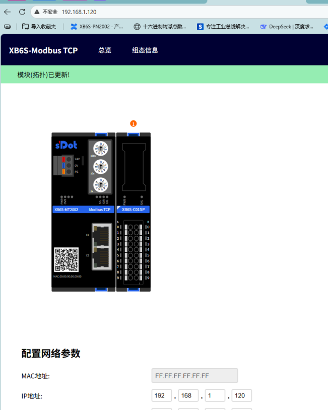
Note: Ensure the PC's IP address is in the same subnet as the coupler (192.168.1.x), otherwise the configuration page cannot be accessed.
III. Configure XB6S-C01SP Free Port Mode
This is the core step. The reason for each parameter setting is explained below.
1. Enter Module Parameter Page
In the Web configuration interface, click on the XB6S-C01SP module to enter its parameter configuration page. The parameters in this example are as shown below.
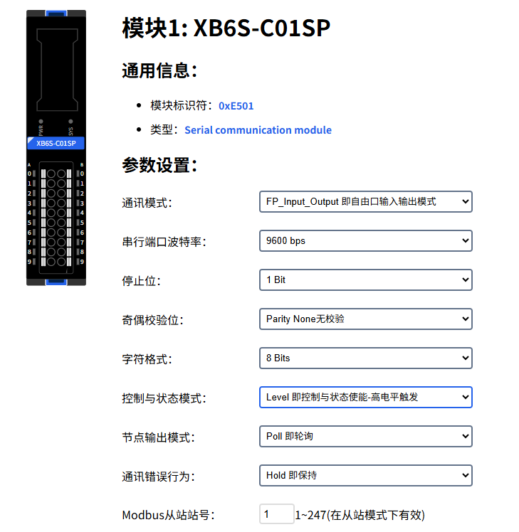
Important: Set Communication Error Behavior to "Hold". This must be done first.
In free port mode, if the configured number of read bytes does not match the actual number of bytes received, the module reports a communication error. If the error behavior is set to the default "Clear", data will be immediately cleared when an error occurs, causing data loss before you can read it. After setting to "Hold", even if an error occurs, the last valid data remains in the register and will not be cleared.
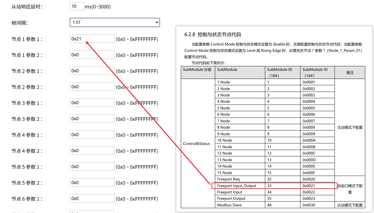
2. Configure Control Node Code
In Node 1 → Parameter 1, set the control node code to 0x21.
This value selects the free port input/output mode with control word. "With control word" means the host computer can trigger data transmission/reception via the control word, rather than the module deciding on its own. 0x21 is the fixed code for this mode; just enter it directly.
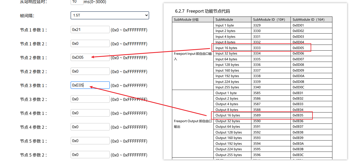
3. Configure Input/Output Bytes
In Node 2 → Parameter 1, configure the number of input bytes. In Node 3 → Parameter 1, configure the number of output bytes. The number of input/output bytes depends on the actual data volume of your serial device. This example uses 16 bytes each for input and output.
"Input" and "Output" are from the coupler's perspective:
● Input = data sent from the serial device to the coupler (uplink, coupler receives)
● Output = data sent from the coupler to the serial device (downlink, coupler transmits)
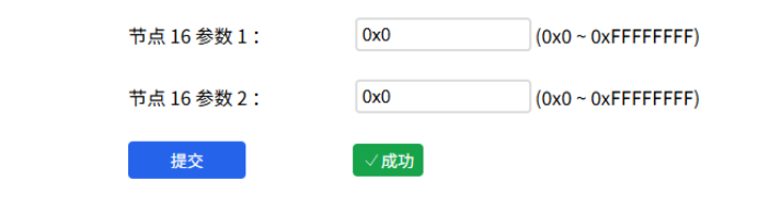
4. Submit and Apply
After parameter configuration, click Submit and Apply. The coupler will save and apply the new configuration.
IV. Data Address Mapping and Read/Write
After configuration, you need to know the data addresses in Modbus TCP to correctly read and write.
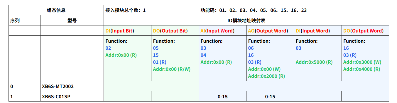
View Data Address
On the coupler's Web interface, go to the configuration information page to view the data start address of the XB6S-C01SP module.
Uplink/Downlink Data Structure
In free port input/output mode, data is divided into uplink and downlink parts:
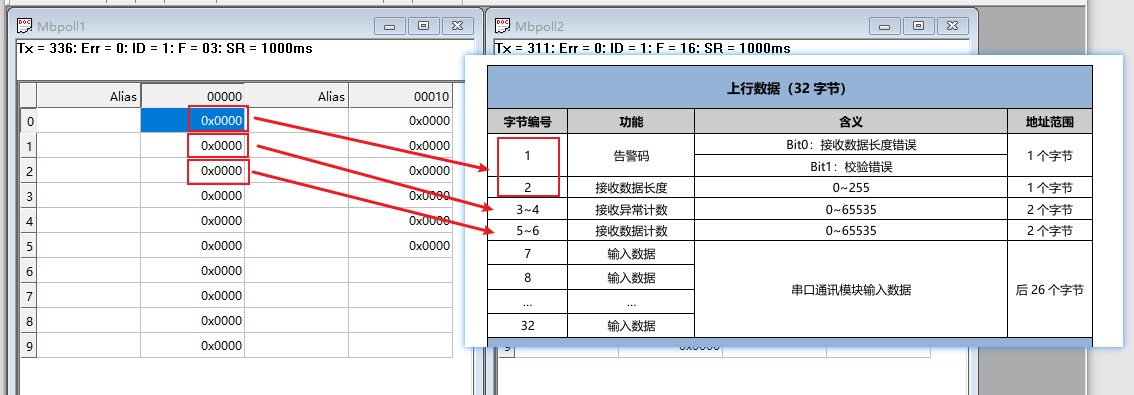
Uplink data (serial → Modbus TCP): Data sent from the serial device is mapped to Modbus TCP input registers. The host computer reads these registers to obtain serial data. The data structure is as shown.
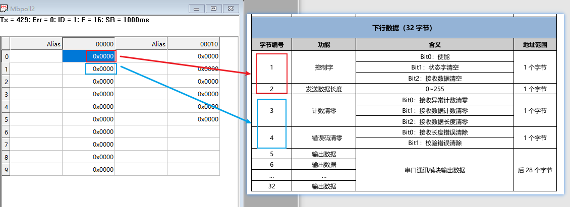
Downlink data (Modbus TCP → serial): The host computer writes to Modbus TCP holding registers, and the data is sent via serial to the serial device. The data structure is as shown.
V. Test Verification
Use Modbus Poll + serial tool to simulate the complete transmission/reception loop and confirm whether the configuration is effective.
Test Tools
● Modbus Poll software: acts as a Modbus TCP master to read/write the coupler's registers
● Serial debugging tool: via USB to RS232 serial cable, simulate serial device data transmission/reception
Modbus Poll Read/Write Configuration
In Modbus Poll, establish separate read connection and write connection, pointing to the coupler's IP address and the corresponding register addresses.
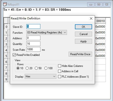
Read Settings
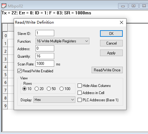
Write Settings
Trigger Mode: High-Level Trigger
In this example, the control mode is set to high-level trigger. After enabling the control word, the module continuously transmits/receives serial data. If your scenario requires on-demand triggering (e.g., sending only one frame each time), you can choose rising-edge trigger mode.
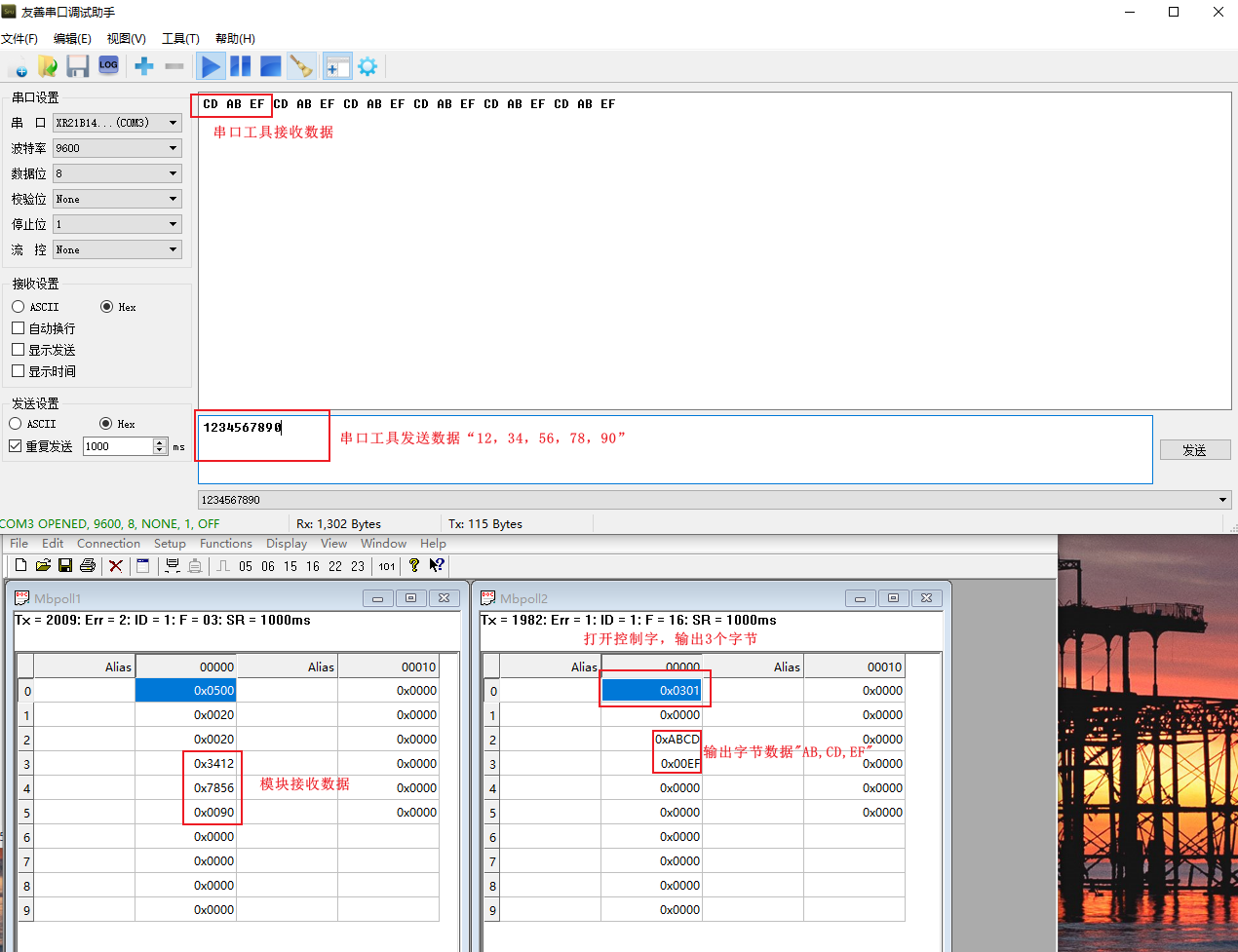
Verification Result
Send data in the serial tool; the Modbus Poll read window shows the corresponding register values updated. Conversely, write data in Modbus Poll; the serial tool receives the corresponding content. Bidirectional transparent transmission verification passed.
VI. Additional Notes and Common Issues
About Communication Error Behavior: It is strongly recommended to set it to "Hold" in free port mode. If set to "Clear", when the serial data frame length is not fixed, errors will almost inevitably cause data loss.
About Byte Count Configuration: The number of input/output bytes should be greater than or equal to the maximum length of a single data frame from your actual serial device. Setting too few bytes will truncate data; setting more bytes does not affect functionality but occupies additional register space.
About Trigger Mode Selection:
● High-level trigger: continuous transmission/reception after control word is set to 1, suitable for scenarios requiring real-time transparent transmission (e.g., sensors continuously reporting)
● Rising-edge trigger: sends one frame each time the control word transitions from 0→1, suitable for on-demand transmission scenarios (e.g., sending commands to a device)
Free Port vs. Modbus RTU Mode: If your serial device itself supports the Modbus RTU protocol, it is recommended to use the module's Modbus RTU gateway mode for simpler configuration. Free port mode is suitable for serial devices with non-standard or custom protocols.