XBF4-EC04A Complete Troubleshooting Guide
Article Overview
1. Applicable Product
Solidot Discrete I/OXBF4-EC04A+ Loaded I/O Modules
2. Problem Scenario
XBF4-EC04A or loaded discrete I/O modules cannot communicate
3. Troubleshooting Dimensions
Physical link / Configuration / Power-up sequence / Power supply / Hardware failure / Interference
4. Troubleshooting Entry Point
First check the indicator status, then locate the cause using the corresponding guide
The XBF4-EC04A is a Solidot discrete I/O EtherCAT coupler. On the top of the module there are two RJ45 EtherCAT ports for communication with the EtherCAT master controller. On the front there are four RJ45 expansion ports, each of which can connect up to 16 discrete I/O modules in series (the modules have DIP switches for station addresses 0–F, addresses must be unique within the same link). The four ports can expand to a total of up to 32 discrete I/O modules.
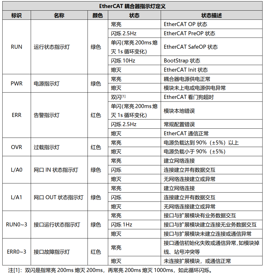
XBF4-EC04A Coupler Indicator Diagram:
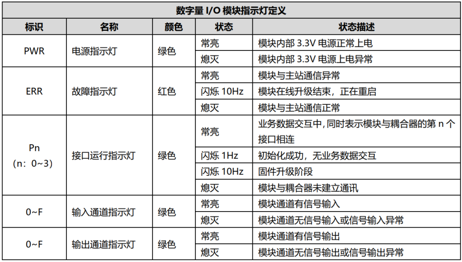
Discrete I/O Module Indicator Diagram:
1. EtherCAT Protocol Layer Physical Network Cable Disconnection
Q: Fault Phenomenon
XBF4-EC04A L/A0 and L/A1 LEDs are both off.
A: Solution
• Check whether the network cable between XBF4-EC04A and the master is normal and whether the connectors are firmly inserted (Cat5e or better finished cables are recommended).
• Check whether the PLC and XBF4-EC04A Ethernet ports are used correctly, ensuring the IN and OUT ports are not swapped.
• If the PLC software supports automatic slave scanning, try scanning to see if XBF4-EC04A can be detected.
2. Bus Layer Physical Network Cable Disconnection
Q: Fault Phenomenon
XBF4-EC04A RUN n (n: 0–3) LED off, ERR n (n: 0–3) LED off.
Discrete I/O module PWR LED, ERR LED, Pn (n: 0–3) LEDs are all off.
A: Solution
• Check whether the network cable between the discrete I/O module and XBF4-EC04A is normal and whether the connectors are firmly inserted (Cat5e or better finished cables are recommended).
• Check the wire sequence of the RJ45 connectors at both ends of the homemade or finished cable. A straight-through cable with the same sequence on both ends is sufficient; crossover is not required.
3. Terminal Resistor Not Installed
Q: Fault Phenomenon
Discrete I/O module Pn (n: 0–3) LED flashes or is off.
A: Solution
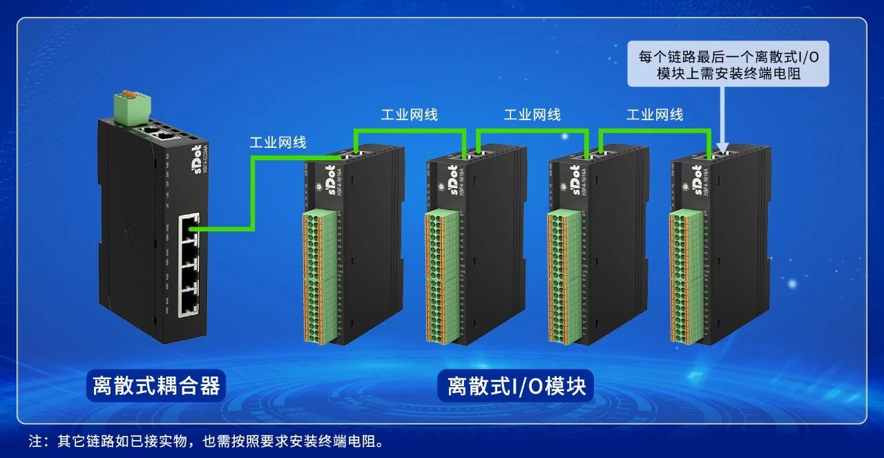
• Check whether a terminal resistor is installed on the last discrete I/O module in the link (the terminal resistor is shipped with the coupler by default). See the installation example diagram below.
• For the C3 series valve island, the terminal resistor is a separate accessory, model XBF-C3FD-ZDDZ.
4. I/O Module DIP Switch Station Address Conflict
Q: Fault Phenomenon
XBF4-EC04A RUN n (n: 0–3) LED off, ERR n (n: 0–3) LED steady on.
Discrete I/O module PWR LED steady on, ERR LED and Pn (n: 0–3) LEDs off.
A: Solution
Check whether there is a DIP switch station address conflict among discrete I/O modules in the same link.
5. Configuration Mismatch with Physical Modules, or Incomplete Configuration
Q: Fault Phenomenon
XBF4-EC04A RUN n (n: 0–3) LED flashes, ERR n (n: 0–3) LED off.
Discrete I/O module PWR LED steady on, ERR LED off, Pn (n: 0–3) LED flashes.
A: Solution
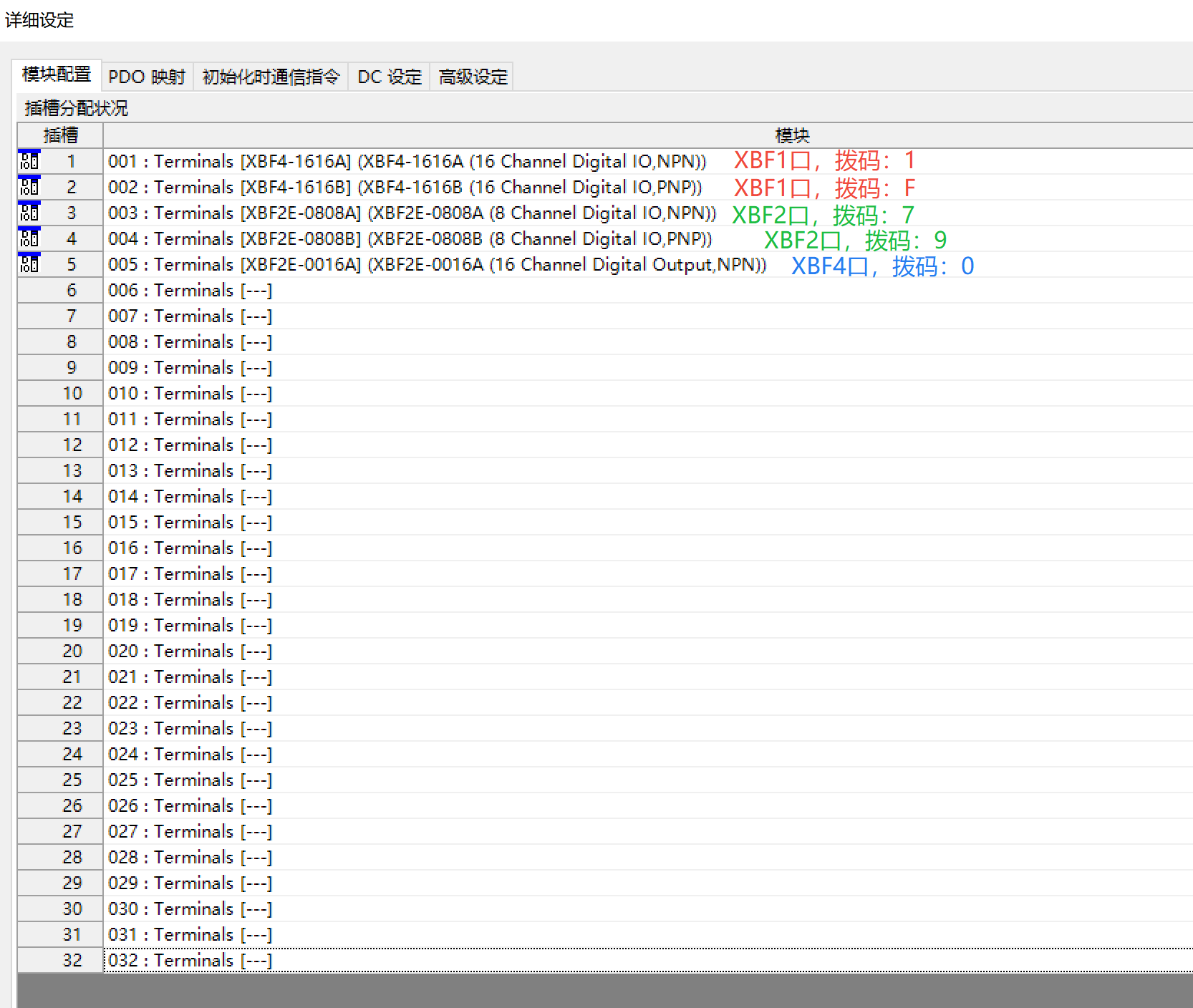
• Check the configuration for the four XBF ports on the front of the XBF4-EC04A. Follow these rules: first configure port 1 according to the actual module types connected, in ascending order of their DIP switch addresses; then configure port 2, port 3, and port 4 in the same manner.
Example as follows:
Port 1 has two modules with DIP switch addresses 1 and F → configure corresponding types in slots 1 and 2.
Port 2 has two modules with addresses 7 and 9 → configure in slots 3 and 4.
Port 3 has no module.
Port 4 has one module with address 0 → configure in slot 5.
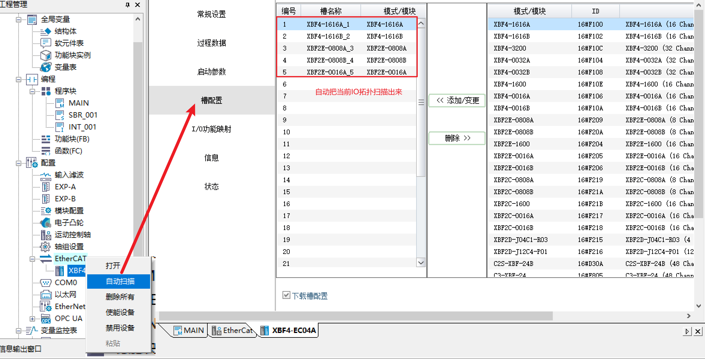
• If the master supports automatic scanning (e.g., AutoShop platform), simply click "Auto Scan" and the system will automatically complete the configuration without manual slot setup.
6. Incorrect Operation: Coupler Powered On Before Connecting I/O Module Cables and Setting DIP Switches
Q: Fault Phenomenon
XBF4-EC04A RUN n (n: 0–3) and ERR n (n: 0–3) LEDs are both off.
Discrete I/O module PWR LED steady on, ERR LED and Pn (n: 0–3) LEDs off.
A: Solution
• The correct procedure is: with XBF4-EC04A powered off, first complete the following three steps:
① Set the DIP switches on each discrete I/O module;
② Install the terminal resistor on the last discrete I/O module in each link;
③ Connect the discrete I/O module network cables to XBF4-EC04A;
After these three steps are completed, then power on XBF4-EC04A. If the operation sequence was incorrect, power cycle the XBF4-EC04A to restore normal operation.
7. Power Supply Wiring Anomaly
Q: Fault Phenomenon
XBF4-EC04A PWR LED is off.
A: Solution
• Power the module according to the correct wiring method and confirm the PWR LED lights up.
• If the power supply rises in a stepped manner (unstable voltage), the module may not start properly. Re-power and ensure stable output.
8.XBF4-EC04A Coupler Failure
Q: Fault Phenomenon
After multiple power-ons, the coupler PWR LED never lights up, but a multimeter measures normal power supply.
XBF4-EC04A has only the PWR LED steady on; all other indicators are off.
XBF4-EC04A has no discrete I/O modules connected, and after power cycling, the ERR n (n: 0–3) LEDs remain steadily on.
A: Solution
• The above phenomena indicate a coupler failure; the coupler needs to be replaced.
9. Discrete I/O Module Failure
Q: Fault Phenomenon
After multiple power-ons, the I/O module PWR LED never lights up, while power and network cables are confirmed normal.
Discrete I/O module has only the PWR LED steady on; ERR LED and Pn (n: 0–3) LEDs are all off.
A: Solution
• The above phenomena indicate a discrete I/O module failure; the module needs to be replaced.
10. Master PLC Failure
Q: Fault Phenomenon
The PLC cannot switch its current operating state, or bus alarms occur frequently.
A: Solution
• Refer to the product manual of the corresponding PLC model for troubleshooting. For detailed information about the current state, consult the controller manufacturer.
• Confirm that PLC resources are sufficient to avoid communication anomalies caused by overloading too many modules.
11. Strong Interference Causing Disconnection or Communication Failure
Q: Fault Phenomenon
Packet loss on the bus communication, XBF4-EC04A RUN and ERR LEDs flash, triggering communication alarms.
A: Solution
• Interference usually comes from two aspects: power side and communication side. Identify and keep away from interference sources such as high-power inverters, servo motors, and their drives.
• Add ferrite cores to the network cables to effectively suppress high-frequency interference.
• Use shielded network cables whenever possible.
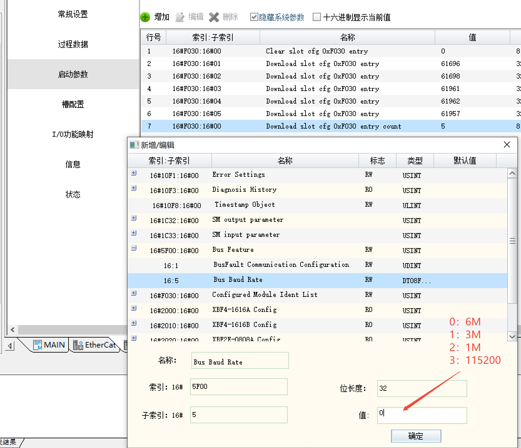
• Appropriately reduce the baud rate of XBF4-EC04A (default maximum 6 MHz). Optional values: 3 MHz, 1 MHz, or 115200 bps.
Setting method:
Add index 5F00, subindex 05, parameter value:
0 (6 MHz), 1 (3 MHz), 2 (1 MHz), 3 (115200 bps)