Knowledge

After completing the configuration of the 4-port distributor in Sysmac Studio, how to add the device on port X4
Article Overview
1. Applicable Products
SW4-ECP04A(metal housing) /SW4-ECP04 (plastic housing)
2. Configuration Tool
Omron Sysmac Studio
3. Core Issue
The location of port X4 in the configuration interface is not obvious; users are unsure how to add devices to this port.
4. Key Solution
When double-clicking to add a device, the lower part of the configuration pop-up window corresponds to port X4. Click the "X4" button to complete the addition.
5. Reason
Port X4 corresponds to the connection position directly below the distributor in the topology, so it is displayed at the lower end of the interface.
After importing the configuration file of the Solidot 4-port EtherCAT distributor (SW4-ECP04A/metal housing or SW4-ECP04/plastic housing) into Omron Sysmac Studio and completing the configuration, how should devices be added to port X4? How is this port displayed in the interface?
This is a common point of confusion for users accustomed to the usual 1-in-3-out (OUT1–OUT3) addition method – in the configuration interface, port X4 is not displayed as an independent OUT label but is located directly below the distributor node. This article uses the XB6S series EtherCAT coupler XB6S-EC2002 as an example to explain the display rule and addition operation for port X4.

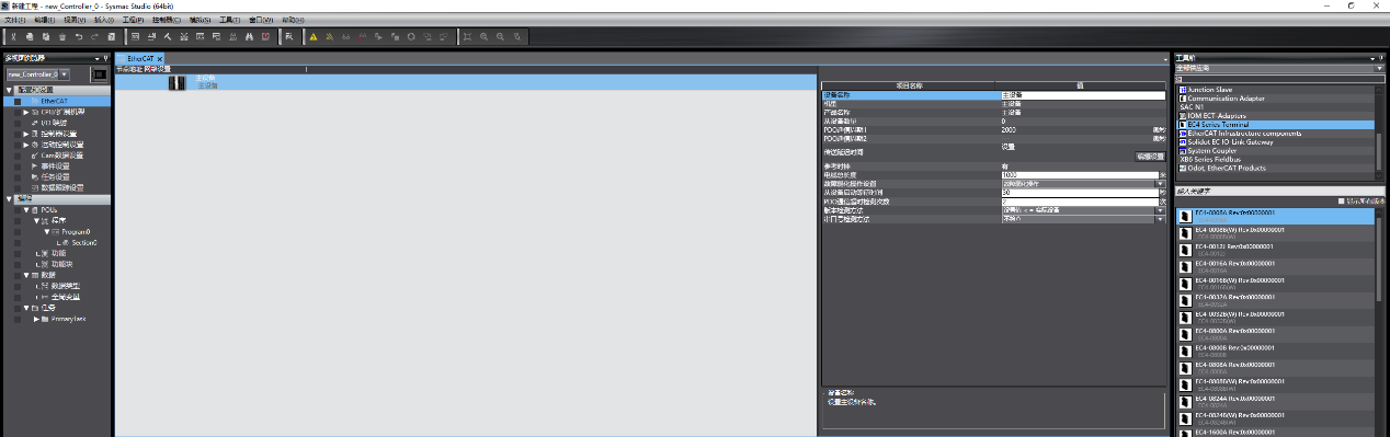
I. Create a New Project
Create a new project in Omron Sysmac Studio, and set the PLC model and firmware version according to the actual hardware.
II. Find the 4-Port Distributor in the Toolbox and Add It
Find the 4-port distributor of the corresponding model in the Sysmac Studio toolbox.
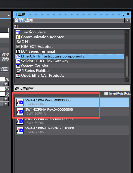
Double-click the distributor or drag it below the master device node to add the distributor to the configuration.
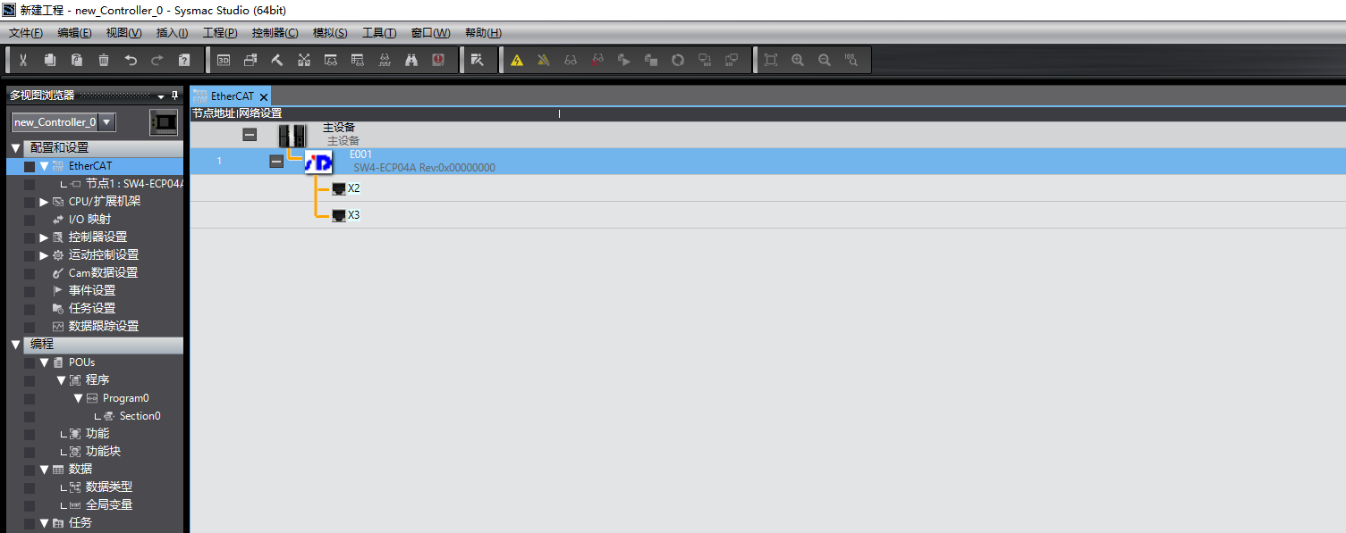
Note: The Solidot 4-port distributor comes in two models: metal housing SW4-ECP04A and plastic housing SW4-ECP04. The configuration must match the actual hardware model. Selecting the wrong model will cause a mismatch between the configuration and the physical device. Please verify the model name before adding.
III. Add EC Devices to OUT1–OUT3 Under the Distributor
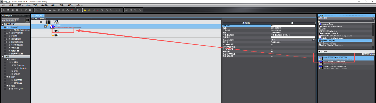
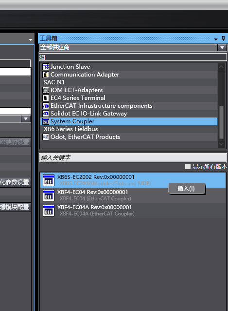
Drag an EC device (in this example, the XB6S series EtherCAT coupler XB6S-EC2002 ) to the corresponding OUT port node of the distributor, or right-click the corresponding OUT port and select "Add Device" to add the device to OUT1–OUT3 ports.
IV. Display Position and Addition Method for Port X4
Port X4 is not displayed as an independent OUT label in the configuration interface. Double-click the target EC device to open the addition pop-up window; the lower area of the pop-up window corresponds to port X4. Click the "X4" button, and the device will be added under port X4.

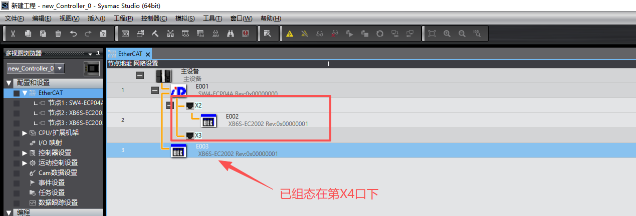
The reason port X4 is located at the lower end of the pop-up window is that, topologically, X4 corresponds to the connection position attached directly below the distributor node – which differs from the lateral topology of OUT1–OUT3. The interface layout is consistent with the physical topology.
Tip: After addition, expand the distributor node in the configuration tree to confirm that the EC device appears under the X4 port entry, verifying that the configuration is correct.