Knowledge

Quick overview
1. Demo product
2. Configuration tool
TIA Portal
3. Core operations
Add GSD file → assign device name and IP → add modules online → download program → configure DIP switch channels
4. Key prerequisites
The corresponding GSD file must be installed in advance; after switching between the alarm version and the standard version and after modifying the DI/DO DIP switches, power must be cycled for the changes to take effect
5. Important notes
DIP switch 0 is disabled by default (standard version); DIP switches 1 ... 5 take effect only on PN5R-1616A+/PN5R-1616B+; in auto-detection mode, a channel receiving an input signal can still output voltage via its Q address and simultaneously triggers an alarm
PN5R-1616B+ is a Solidot integrated horizontal I/O with PROFINET protocol, featuring 16-channel digital PNP input / 16-channel digital PNP input & output compatibility. How do you complete its full configuration in TIA Portal, from GSD file import to device commissioning, and correctly use the configurable input/output channels and DIP switches?
First, it must be clarified that the TIA Portal configuration of PN5R-1616B+ is divided into two stages: first complete the GSD file installation, device name assignment and online module addition, then flexibly set the DI/DO direction of each channel group via the DIP switches. Focusing on this, this article introduces the complete configuration steps, DIP switch configuration rules, alarm version address arrangement and how to view alarms in the standard version.
1. Configuration steps
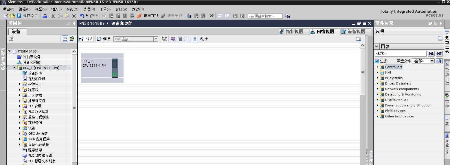
1. Open TIA Portal, create a new project, and add a PLC.
Open TIA Portal, create a new project, and add the corresponding PLC model in the device view.
2. Add GSD file
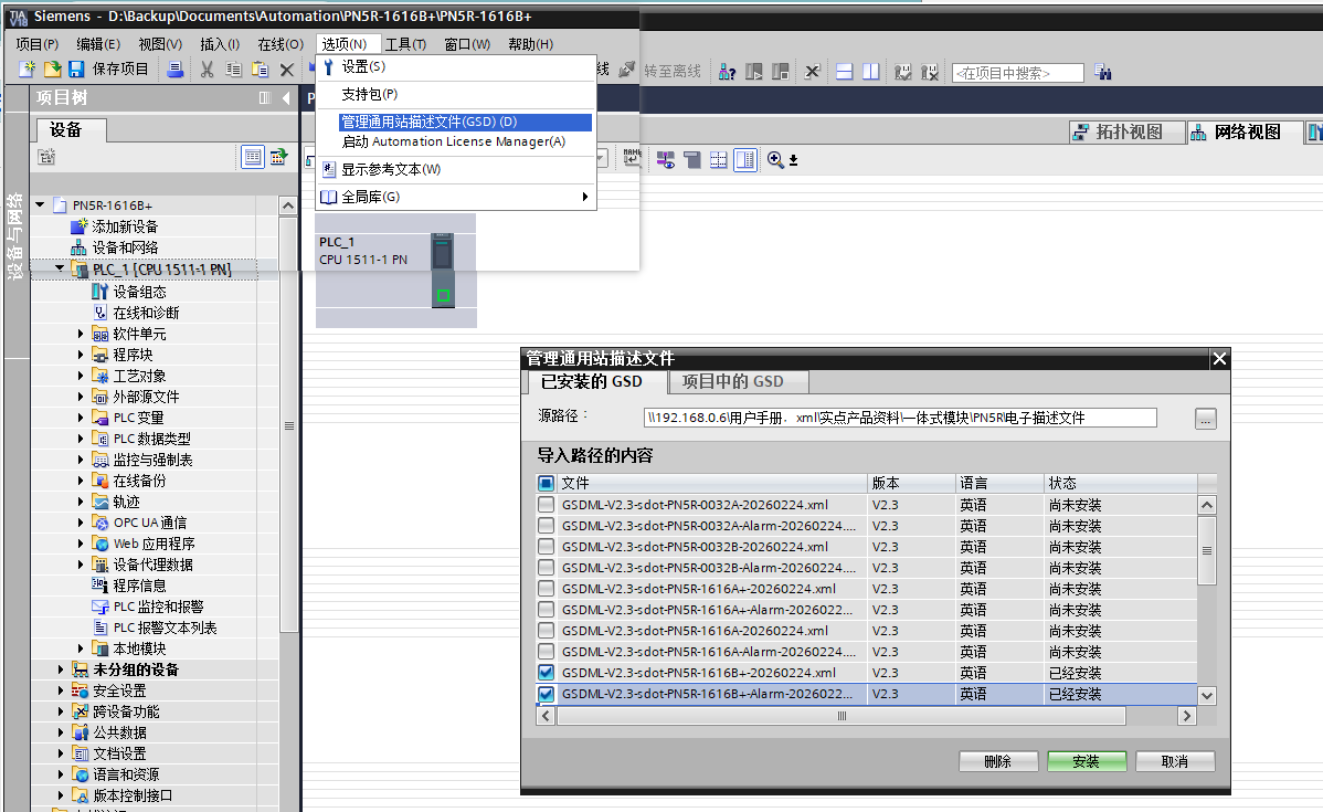
In the menu bar, select "Options" → "GSD File Management", locate the GSD file provided by Solidot (the file name contains PN5R-1616B+), and click "Install". Once installation is complete, the PN5R-1616B+ related modules appear in the hardware catalog.
3. Assign device name
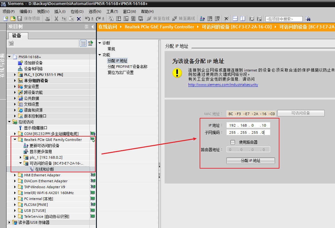
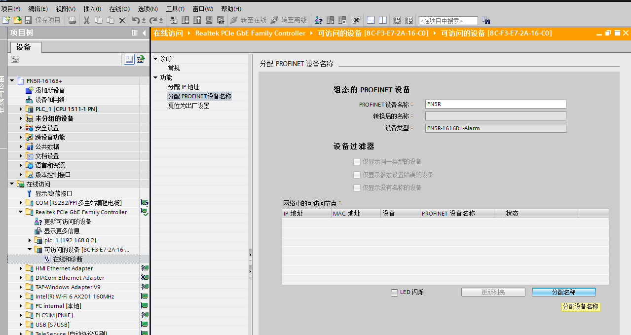
In the project tree, expand "Online access" and perform a search. After locating the I/O module, manually assign a device name and IP address to it.
4. Add module
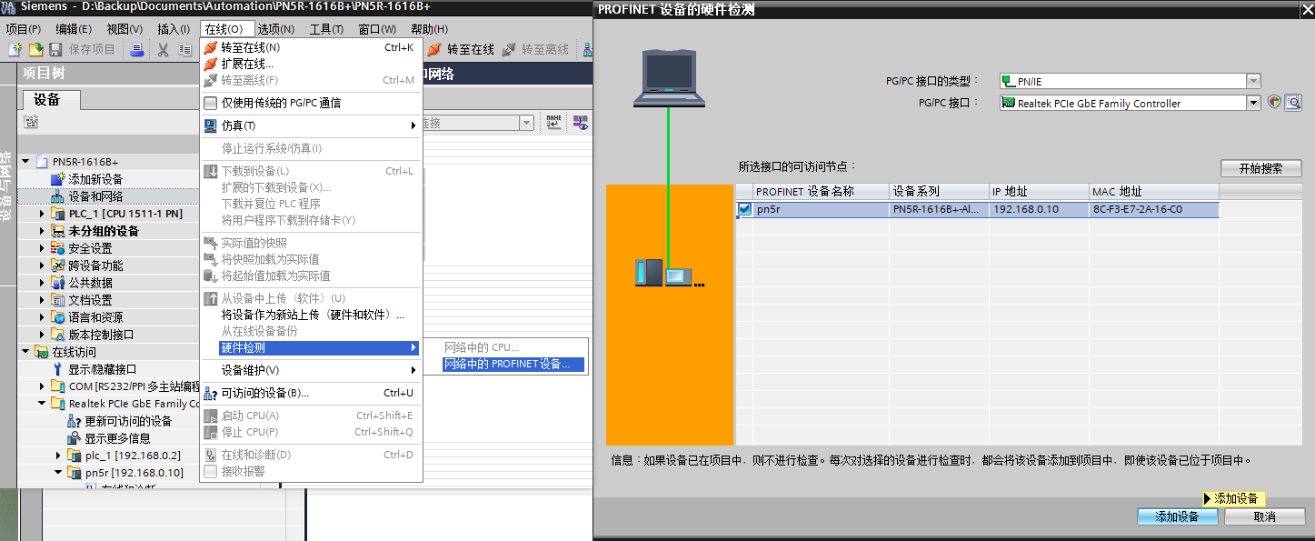
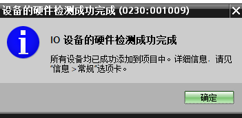
Perform a search via "Online → Hardware detection → PROFINET devices in the network" and add the detected PN5R-1616B+ to the project. Once hardware detection of the device is successful, the software displays "Hardware detection of the I/O device completed successfully. All devices have been added to the project." Click "OK".
5. Click Assign, download the program
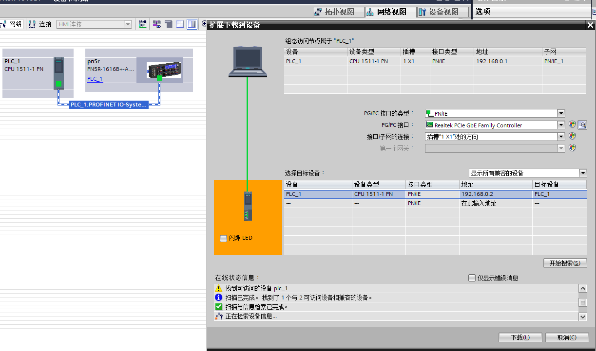
In the network view, confirm the device connections, click "Assign" to complete IP assignment, then download the program to the PLC to complete configuration.
II. DIP switch description
The PN5R-1616B+ module has six DIP switches, 0 to 5. Each DIP switch functions independently, as described below:
DIP switch 0 — alarm version switching
DIP switch 0 is used to switch the entire PN5R series between the alarm version and the standard version; the default is off (i.e., the standard version). The alarm version has two additional bytes of upstream alarm code compared with the standard version. When enabled, the module reports the current fault status in the first two bytes of the upstream data. The alarm codes are defined as follows:
When the digital module is set to the alarm version, the alarm code is reported in the module's upstream data, as shown in the table below.
Error Code | Meaning |
0 x 0000 | No fault |
0 x 0001 | Load-side Voltage Not Connected |
0 x 0002 | DO output error |
0 x 0004 | Firmware is incompatible with the current module model |
0 x 0008 | Firmware Upgrade Error |
0 x 0010 | Parameter Setting Error |
0 x 0020 | When the DI channel auto-detection bit is set to 1, an incorrect operation sets the corresponding DO control address of this channel to 1 |
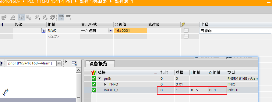
For example, when the load-side voltage is not connected, the alarm code in the monitor table displays as 16#0001.
DIP switches 1-5 — Configurable input/output channels
DIP switches 1 to 5 are dedicated to modules with configurable input/output. Depending on the state of DIP switch 1, there are two operating modes —
When DIP switch 1 is 0 — the DIP switches determine the channel direction
DIP switches 2 to 5 correspond to four channel groups (4 channels each). They set each channel group to DI (input) or DO (output) in binary form:
When binary DIP switch 1 is set to 0, whether a configurable channel is DI/DO is determined by the DIP switch (see the table below); when set to 1, whether a configurable channel is DI/DO is determined by module auto-detection.
Configurable DI/DO DIP switch setting table (effective when binary DIP switch 1 is set to 0) | |
DIP switch 2 setting (binary) | 0: Channels 00 ... 03 are DO outputs |
1: Channels 00 ... 03 are DI inputs | |
DIP switch 3 setting (binary) | 0: Channels 04 ... 07 are DO outputs |
1: Channels 04 ... 07 are DI inputs | |
4 DIP switch setting (binary) | 0: Channels 08 ... 0B are output DO |
1: Channels 08 ... 0B are input DI | |
5 DIP switch setting (binary) | 0: Channels 0C ... 0F are output DO |
1: Channels 0C ... 0F are input DI | |
Notes:
1. To switch between the normal version/alarm version and DI/DO during communication, the entire module group must be powered off and on again after the new settings are made before they take effect.
2. On the PN5R-1616A+/PN5R-1616B+ modules, binary DIP switches 1 to 5 are effective; on the PN5R-0808A+/PN5R-0808B+ modules, binary DIP switches 1 to 3 are effective. On the other digital modules, binary DIP switches 1 to 3/5 have no effect.
When DIP switch 1 is 1 — auto-detection mode
The direction of configurable channels is determined automatically based on the actual wiring, with no manual DIP switch setting required.
Note: With wiring-based auto-detection, a channel connected to an input signal can still output voltage normally via the Q address, and the module triggers an alarm at the same time.
3. Address Arrangement of Configurable input/output modules
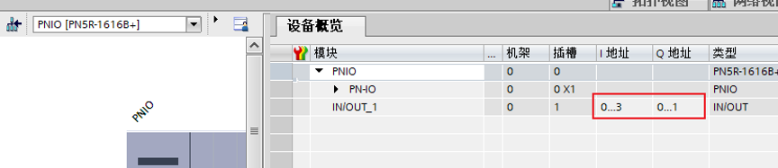
In the Upstream data of the alarm version, the first two bytes are occupied by the alarm code, and the remaining input occupies 4 bytes, corresponding to fixed 16 input points and 16 configurable input/output points; the output is 2 bytes, corresponding to 16 configurable input/output points.
The Upstream data of the normal version contains no alarm code. The input data is 4 bytes, corresponding to fixed 16 input points and 16 configurable input/output points; the output is 2 bytes, corresponding to 16 configurable input/output points.
4. Viewing Alarms in the normal version
The normal version does not display alarms in the Upstream data, but they can be read via the TIA Portal diagnostic function. When an alarm occurs (such as Load-side voltage Not Connected), locate the PN5R-1616B+ module in the device view, double-click the small wrench icon to open the "Online & diagnostics" interface, and view the specific alarm information under "Diagnostics → Standard diagnostics".
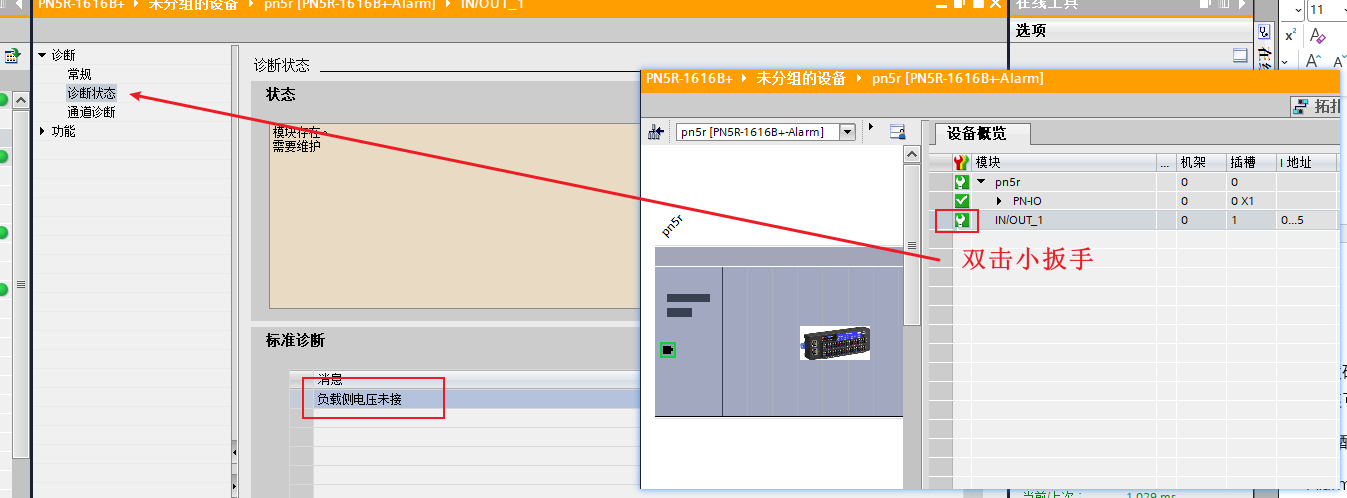
Tip: Alarms in the standard version are not actively reported in the watch table. It is recommended to periodically check the device status via the TIA Portal diagnostic function during commissioning.