Knowledge

Quick overview
1. Applicable slave
XB6S-EI2002, can be combined with I/O modules such as XB6S-3200 and XB6S-0032A
2. Master PLC
Xinje XDH-60T4-E (firmware version: XDH_V3.7.5-20250427)
3. Configuration software
Xinje PLC programming tool software XDPPro, software version: 3.8.0a
4. Core workflow
Modify IP → Install EDS file → Add slave → parameter configuration → device address assignment → download → device monitoring
5. Key prerequisites
The IP network segments of the computer, PLC and coupler must be the same
6. Key notes
The coupler status word/alarm code is enabled by default and occupies 4 bytes of upstream data; if disabled, it does not occupy any address space.
XB6S-EI2002 is a Solidot slice I/O EtherNet/IP coupler that can be used with digital, analog, function modules and other I/O modules. When it is connected as a slave to an Xinje XDH-60T4-E PLC for EtherNet/IP communication, configuration must first be completed in the Xinje programming software XDPPro before data exchange can take place. So what steps are required to complete this communication setup?
This document uses an Xinje XDH-60T4-E + XDPPro 3.8.0a as an example to demonstrate the complete configuration procedure.
Preparations
Xinje PLC model | XDH-60T4-E (firmware version: XDH_V3.7.5-20250427, XDH series PLC) |
Coupler model | XB6S-EI2002(EtherNet/IP protocol coupler) |
I/O module | XB6S-3200(32-point digital input, input NPN/PNP compatible), XB6S-0032A(32-point digital output, output NPN) XB6S-CVR00(End cover) |
Configuration software | Xinje PLC programming tool software XDPPro, software version: 3.8.0a |
Network topology
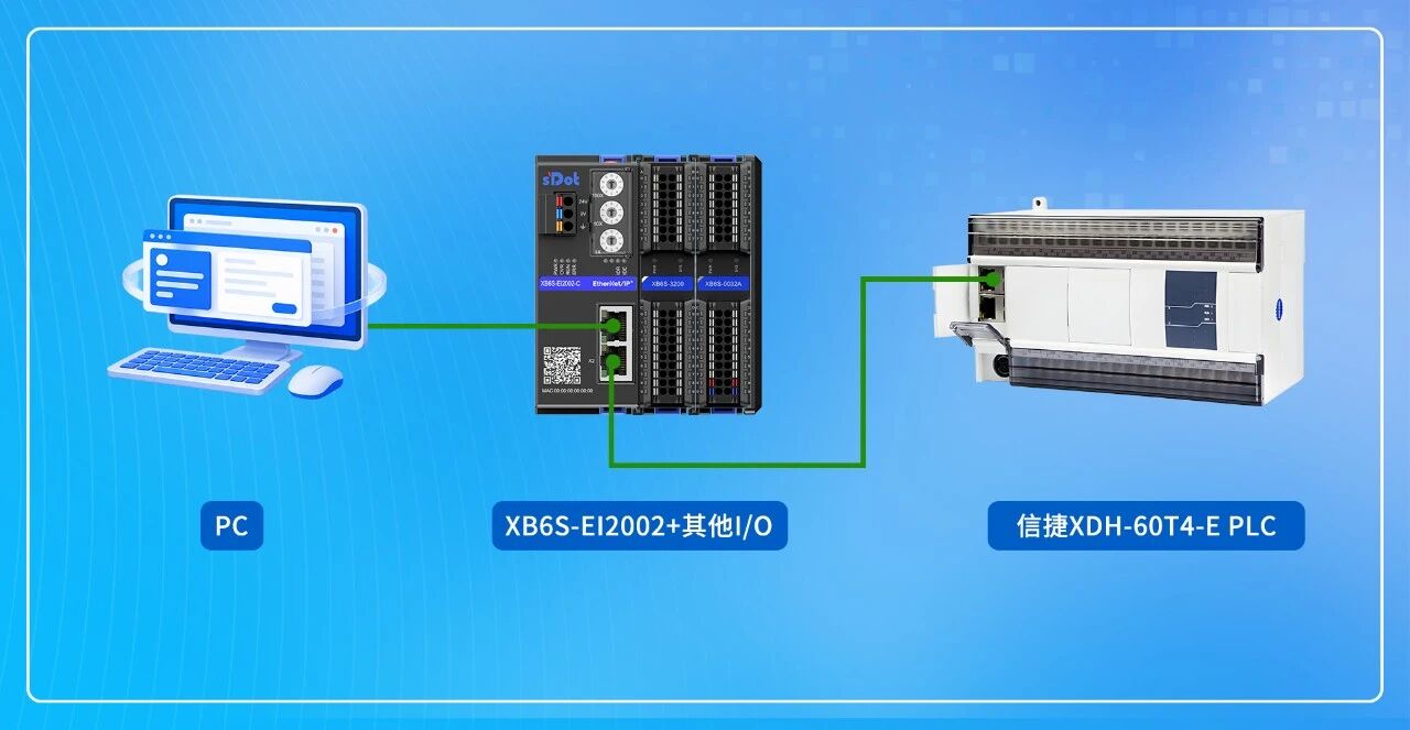
The host computer (with XDPPro installed) and the Xinje XDH-60T4-E PLC are connected via Ethernet cable to the coupler XB6S-EI2002, which is equipped with I/O modules such as XB6S-3200 and XB6S-0032A, forming an EtherNet/IP communication network.
Configuration in the Xinje XDPPro software
1. Change the IP address of the slave coupler
Download the IP setting Tool from the Solidot website, or use the IO Config Tool host software to change the IP address. The module's factory default IP address is 192.168.0.120.
Note: The IP addresses of the computer, PLC, and coupler must be on the same network segment.
2. Install the EDS file
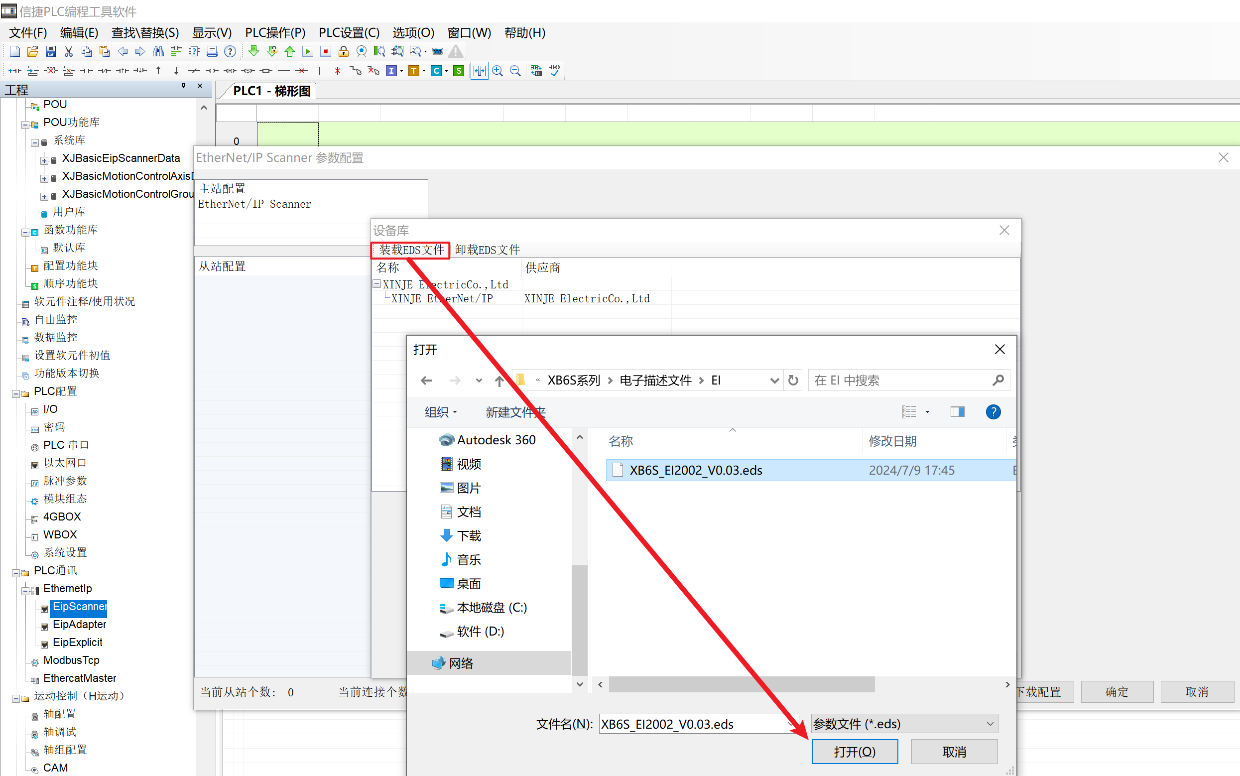
Open the Xinje software, double-click [EipScanner] → right-click [EtherNet/IP Scanner] to add a device → [Load EDS file].
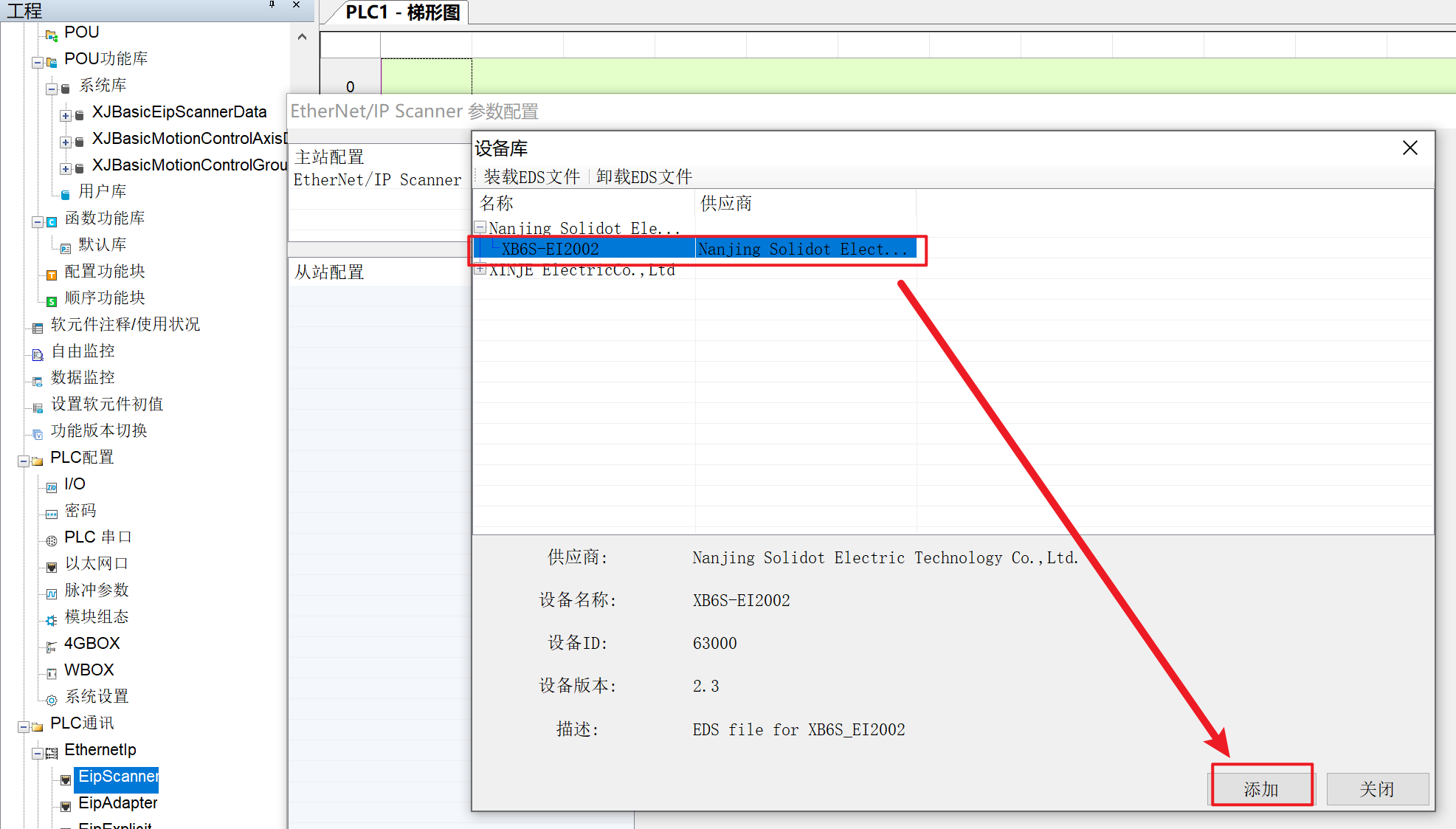
3. Add an EtherNet/IP slave
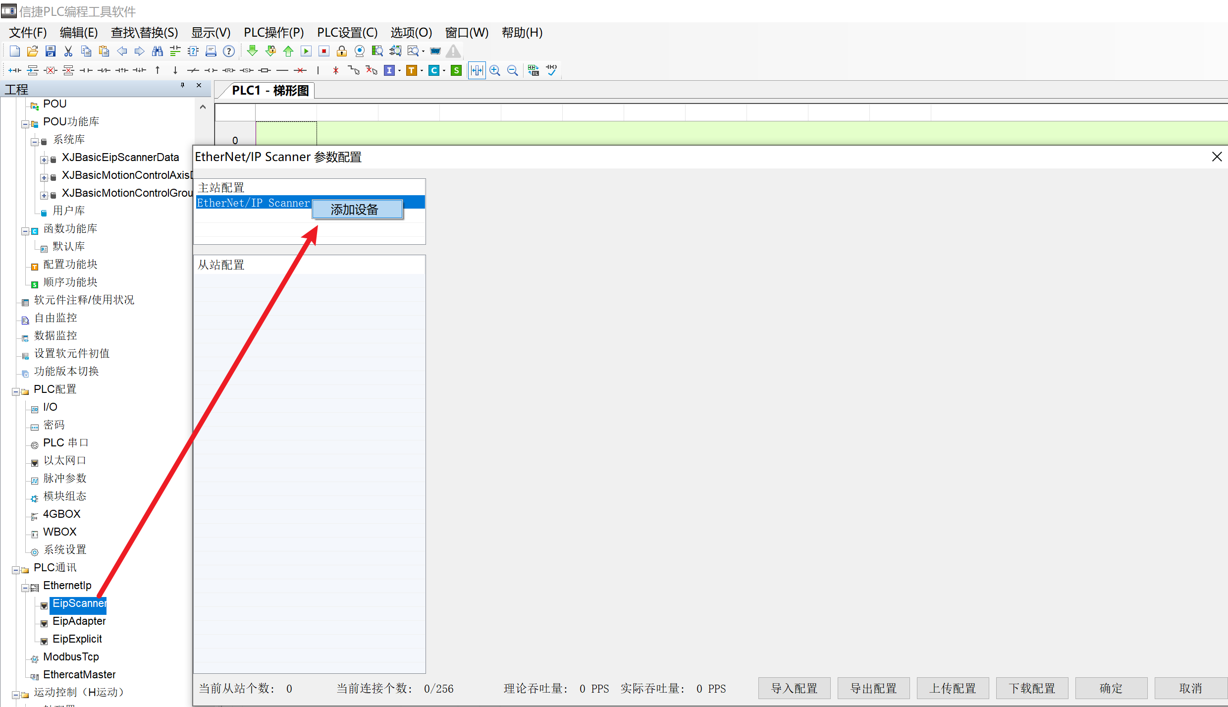
Double-click [EipScanner] → right-click [EtherNet/IP Scanner] to add a device; select the corresponding slave → [Add].
4. Parameter configuration
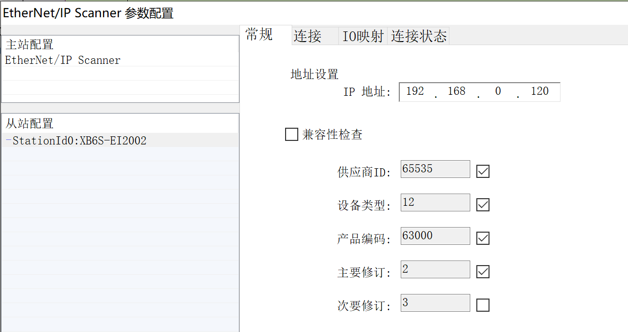
Click [General] and set the slave IP address. The default is 192.168.0.120.
Click [connection] and [Add] to set the upstream and downstream data lengths and the input/output start address mapping.
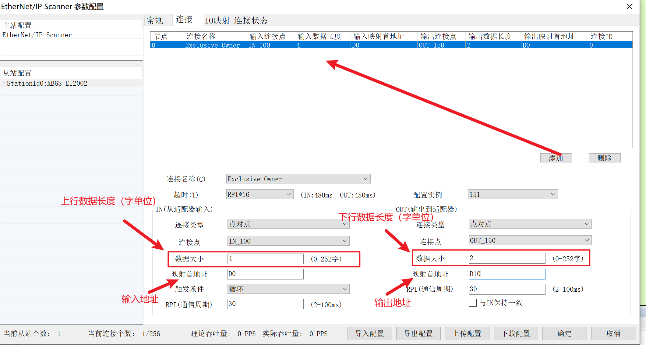
(1) The IO Config Tool host software can be used to automatically obtain the upstream and downstream byte lengths, which are then entered in the PLC-side [connection] → [data size].
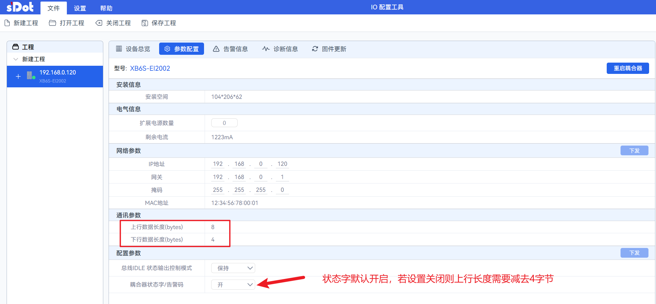
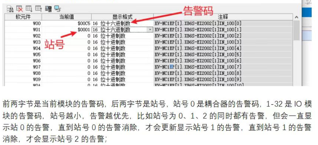
Coupler status word/alarm code definition (occupies two words): the first status word is the alarm code, and the second status word is the station number. Station number 0 represents the coupler's alarm code, and 1 ... 32 represent the I/O modules' alarm codes. The lower the station number, the higher the alarm priority. For example, if station numbers 0, 1, and 2 all have alarms simultaneously, the alarm for station number 0 will continue to be displayed until the alarm for station number 0 is cleared. Only then will the alarm for station number 1 be displayed, and it will remain until the alarm for station number 1 is cleared, after which the alarm for station number 2 will be displayed.
Category | No. | Error type | Error | Event name | Event code (2#) | Event Code | Event Code | Remedy |
General Error | 2 | Online Firmware Update | 1 | Firmware Upgrade Error | 0000000010000001 | 129 | 0 x 0081 | Try the firmware upgrade again, and check whether there is |
2 | The firmware does not match the current module model | 0000000010000010 | 130 | 0 x 0082 | Check whether the file is correct and whether the module has | |||
3 | Voltage Error | 5 | Load-side Voltage Not Connected | 0000000011000101 | 197 | 0 x 00C5 | Check whether the field-side power supply is connected | |
6 | Channel error | 4 | Channel Overflow/Underflow | 0000000110000100 | 388 | 0 x 0184 | Check whether the input signal of the corresponding channel exceeds the | |
7 | Parameter Error | 0 | Parameter Setting Error | 0000000111000000 | 448 | 0 x 01C0 | Check the module parameter settings | |
63 | X-bus communication | 1 | X-bus Initialization Failure | 0000111111000001 | 4033 | 0 x 0FC1 | Check whether the module connection is normal | |
2 | X-bus Token Timeout | 0000111111000010 | 4034 | 0 x 0FC2 | Check whether the module has any abnormalities or interference | |||
3 | X-bus Module Offline During Operation | 0000111111000011 | 4035 | 0 x 0FC3 | Check whether the module is online or whether interference is present | |||
4 | Parse Data CRC Error | 0000111111000100 | 4036 | 0 x 0FC4 | Check the module for abnormalities or interference | |||
Analog | 1 | 0 | Disconnection | 0010000001000000 | 8256 | 0 x 2040 | Check whether the wiring of the corresponding channel is correct |
(2) Or manually calculate the upstream and downstream byte lengths: when the coupler status word is enabled, the coupler occupies 4 upstream bytes (2 status words); when the coupler status word is disabled, the coupler does not occupy any addresses.
5. Device address assignment
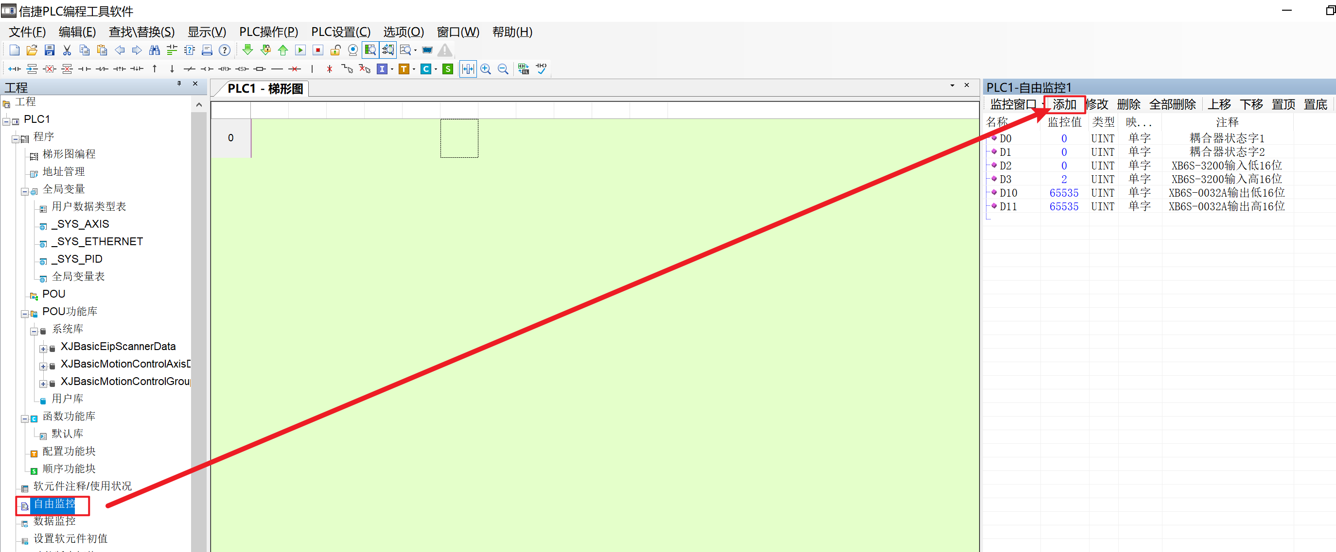
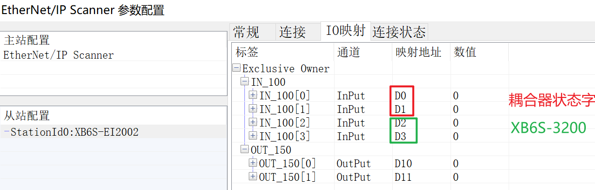
Take the coupler status word enabled as an example: D0-D3
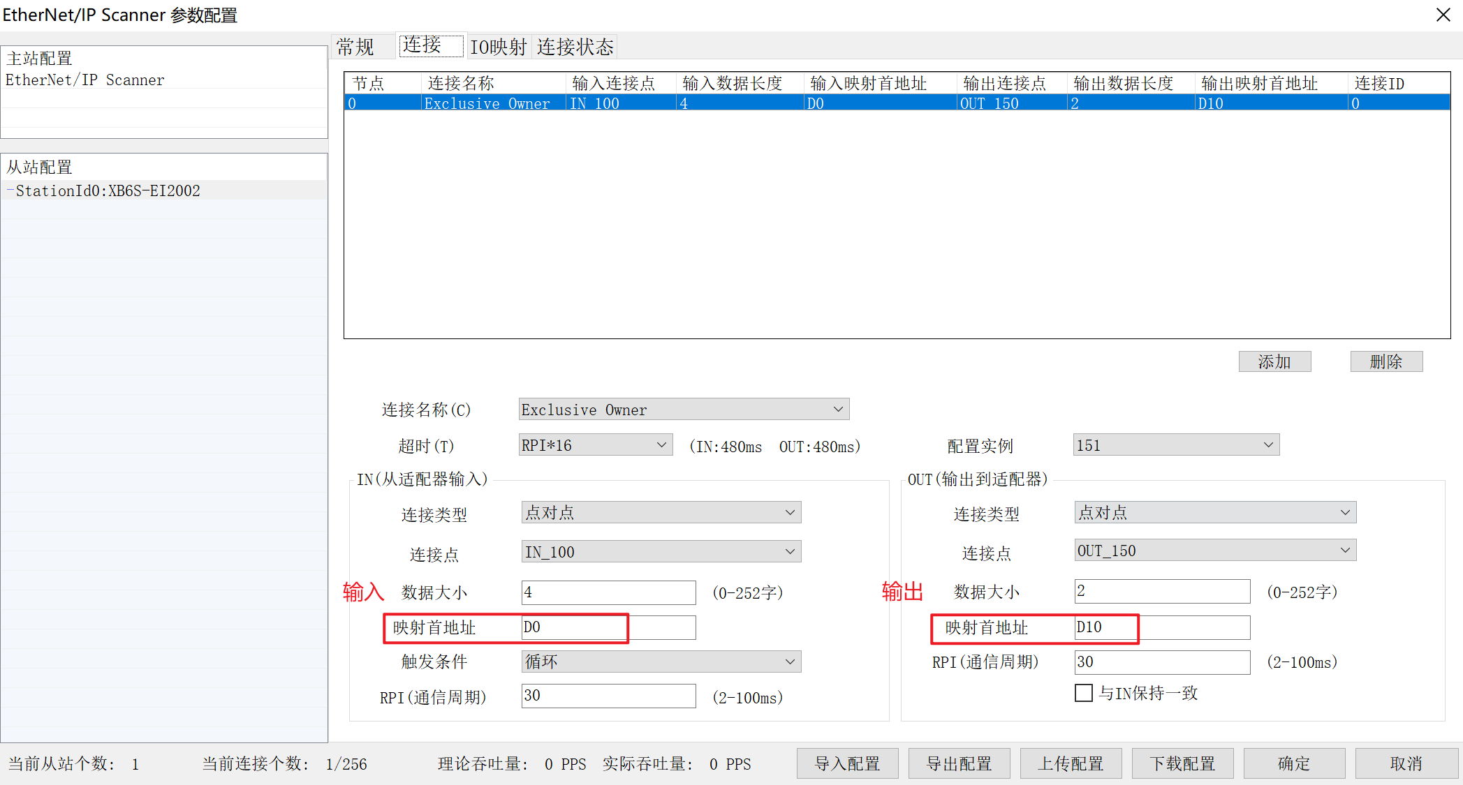
Upstream input address assignment: D0-D3
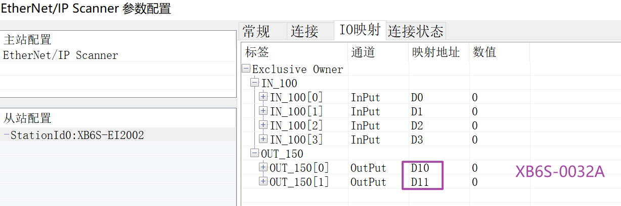
Downstream output address assignment: D10-D11
Once the settings are complete, click [OK].
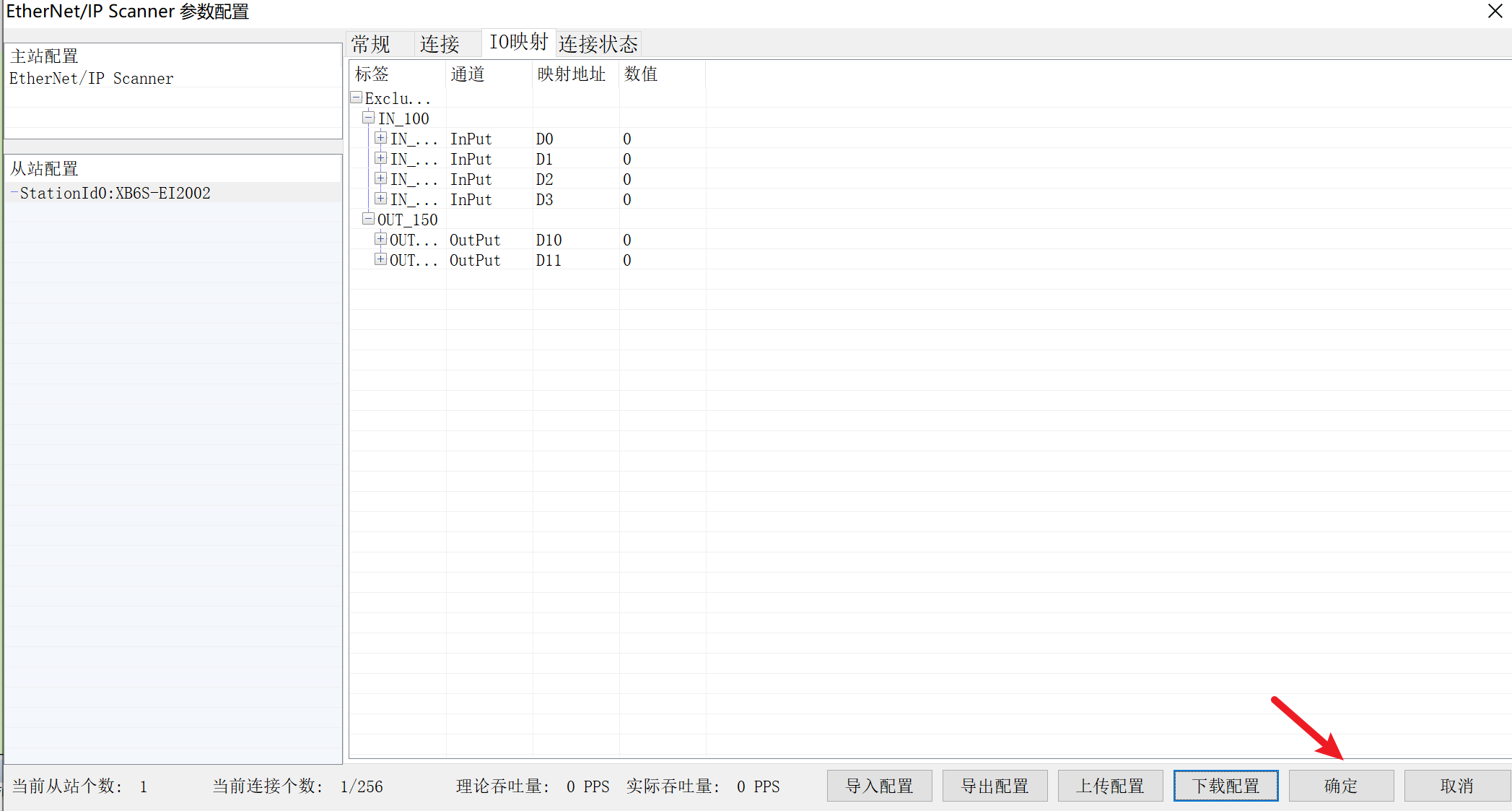
6. Download
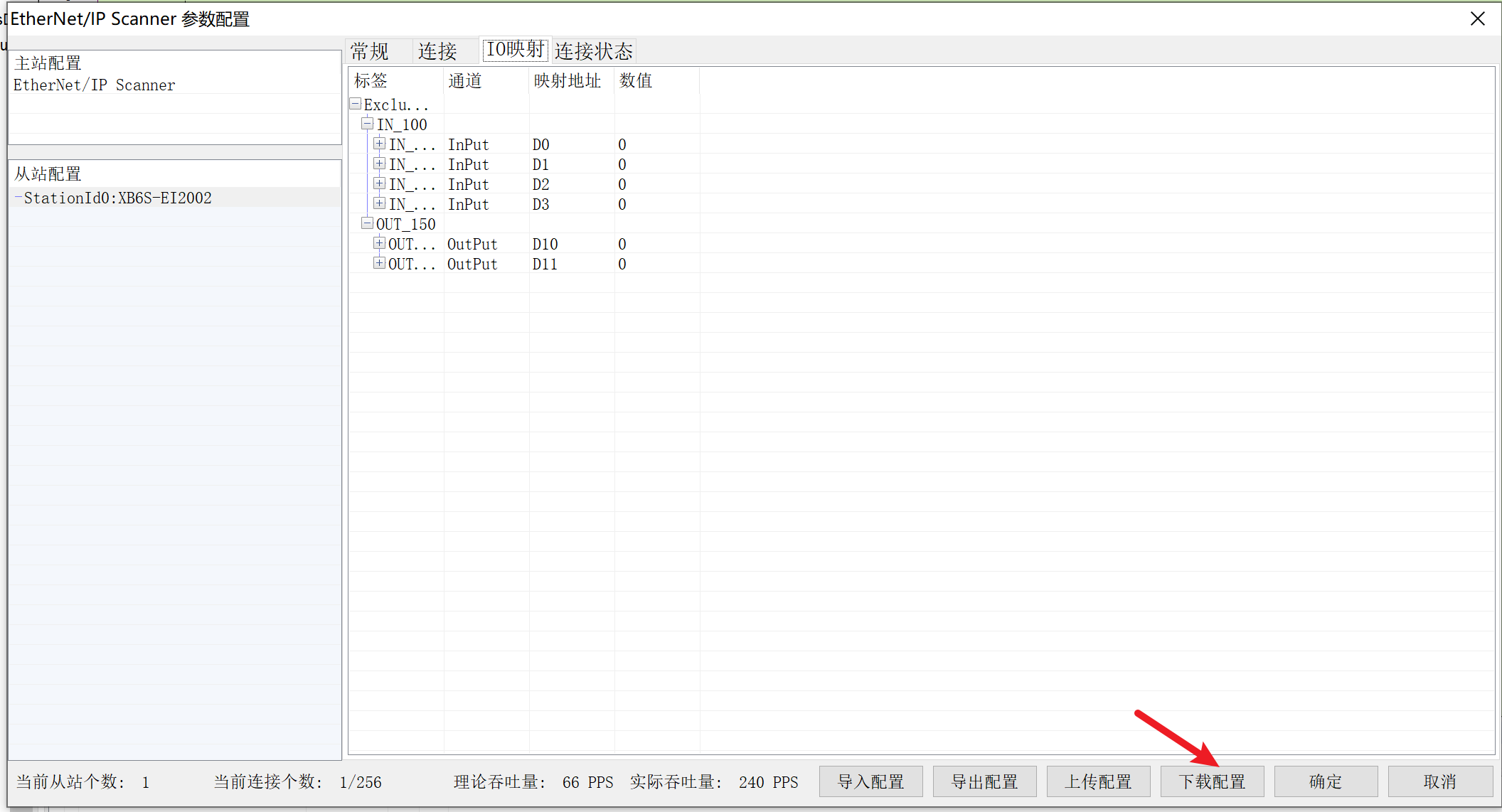
Click [download configuration].
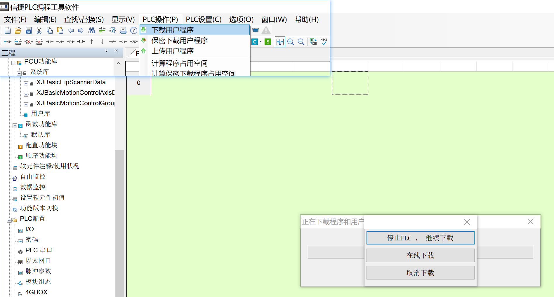
Then go to [PLC operation] → [download user Program] → [online download].
7. Device monitoring
Go to [Free Monitor] → [Add] and enter the input and output addresses to monitor the communication data.