Knowledge

Article at a Glance
1. Demonstration products
2. Communication protocol
PROFINET
3. Configuration tool
TIA Portal
4. Operations covered
Adding master and submodule configuration, modifying port pin definitions, configuring UA power supply, diagnosing communication status, controlling input and output addresses
5. Key notes
Unused ports remain set to standard input; the X00 port pin 2 must be configured as output to supply UA power to the hub
The IOL7A-16CB-M12 is a 16-channel configurable input/output IO-Link HUB from Solidot, which can be connected to a PROFINET network via the IO-Link Master IOL7A-PN01B-8A. How do you complete its hardware configuration in TIA Portal and achieve input/output control of field sensors and loads?
In TIA Portal, you only need to add the configuration for the master and the hub submodule, modify the port pin definitions and configure the UA power supply to use the input/output channels of the IOL7A-16CB-M12. This article describes the steps for adding the hardware configuration, key configuration notes, the PROFINET master process data definitions and the input/output control method.
Steps for adding the hardware configuration
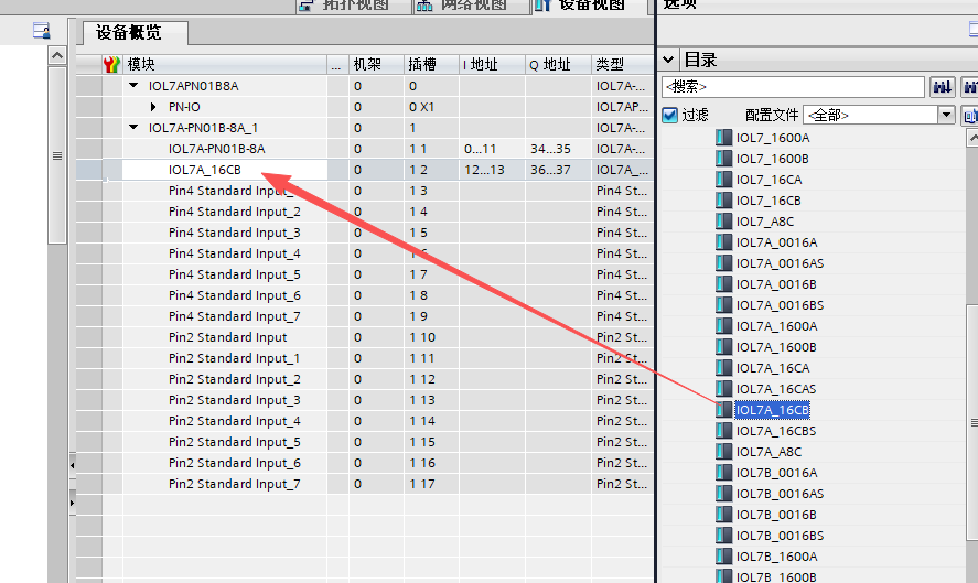
1. In the TIA Portal hardware catalog, locate and add the IOL7A-PN01B-8A IO-Link Master. The master generates default pin 4 and pin 2 definitions for 8 ports, all of type standard input by default.
2. Right-click to delete the default port definitions and select IOL7A-16CB to add the submodule configuration.
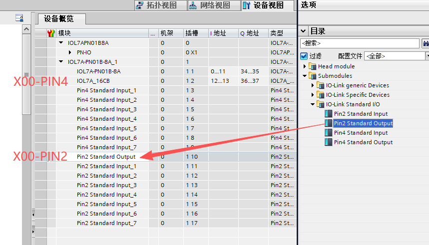
3. Delete the existing pin 2 configuration for the corresponding port and change pin 2 to pin 2 standard output.
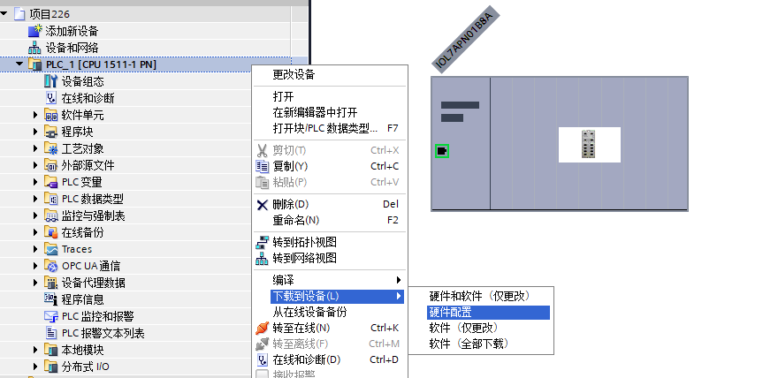
4. Compile the hardware configuration and download it to the PLC.
Key configuration notes
• In this example, only one IOL7A-16CB-M12 is connected to the X00 port of the master; all other ports are left empty. Unused ports remain configured as standard input. If empty ports are not configured properly, the overall operating stability of the device may be affected.
• Purpose of configuring the X00 port pin 2 as output: the pin 2 output channel of the master supplies UA power to the IOL7A-16CB-M12; if the UA indicator on the master is flashing, check this configuration first.
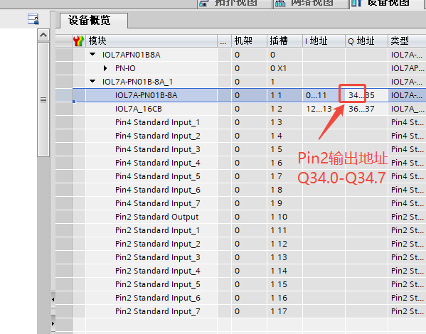
• In this example, the output addresses for pin 2 of all ports X00... X07 are Q34.0... Q34.7. In the program, Q34.0 must be set to 1 for the X00-pin2 port to supply power normally.
PROFINET master process data definition
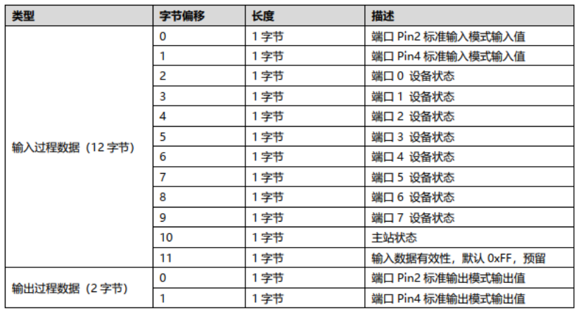
• data definition table for Slot0 of the PROFINET master IOL7A-PN01B-8A model:
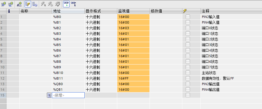
• Communication status determination method: monitor variable %IB2 (port 0 device status byte). When the value is 16#03, port 0 has switched to IO-Link mode and communication is normal.
IOL7A-16CB-M12 input/output control
The IOL7A-16CB-M12 is a self-adaptive IO-Link HUB; the port input/output direction does not need to be configured separately.
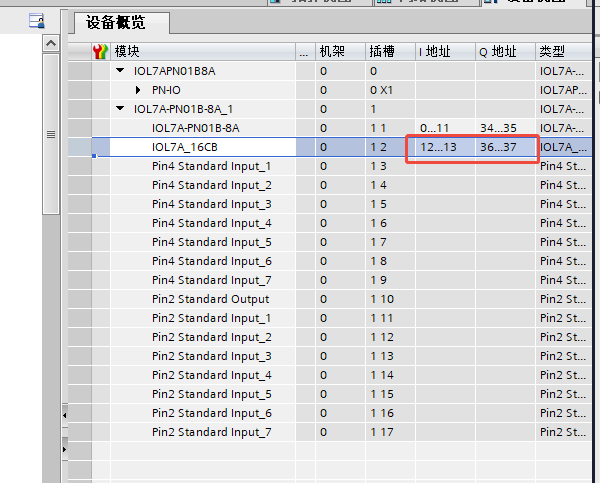
• output control: directly assign a value to the output Q address to drive an external load. The corresponding addresses are Q36.0... Q36.7.
• signal acquisition: external sensor input signals are automatically mapped to I addresses for reading. The corresponding addresses are I12.0... I13.7.