Knowledge


Quick overview
1. Applicable modules
2. Bus protocol
EtherCAT
3. Core content
System-side and load-side power supply wiring, DIP switch modes and compatible channel configuration, configuration selection and PDO data area partitioning, address mapping on mainstream PLC platforms
4. Key prerequisites
DIP switch 0 determines the default mode and the alarm mode; the master configuration model must match the hardware DIP switch state
5. Key notes
After changing the DIP switches, the module must be fully powered off and restarted; system power supply and load power supply must not be mixed or connected together
6. Applicable platforms
Omron, CODESYS, Inovance AutoShop, Keyence
EC5R-1616A+ and EC5R-1616B+ are Solidot integrated 5-series digital I/O modules. In addition to 16 fixed input channels, they provide 16 compatible channels that can be configured as inputs or outputs. The maximum load current per output channel is 0.5 A, making them suitable for on-site I/O expansion in EtherCAT bus control systems.
Using EC5R-1616A+ and EC5R-1616B+ as examples, this article covers module wiring, DIP switch definitions, configuration, and PDO address mapping.
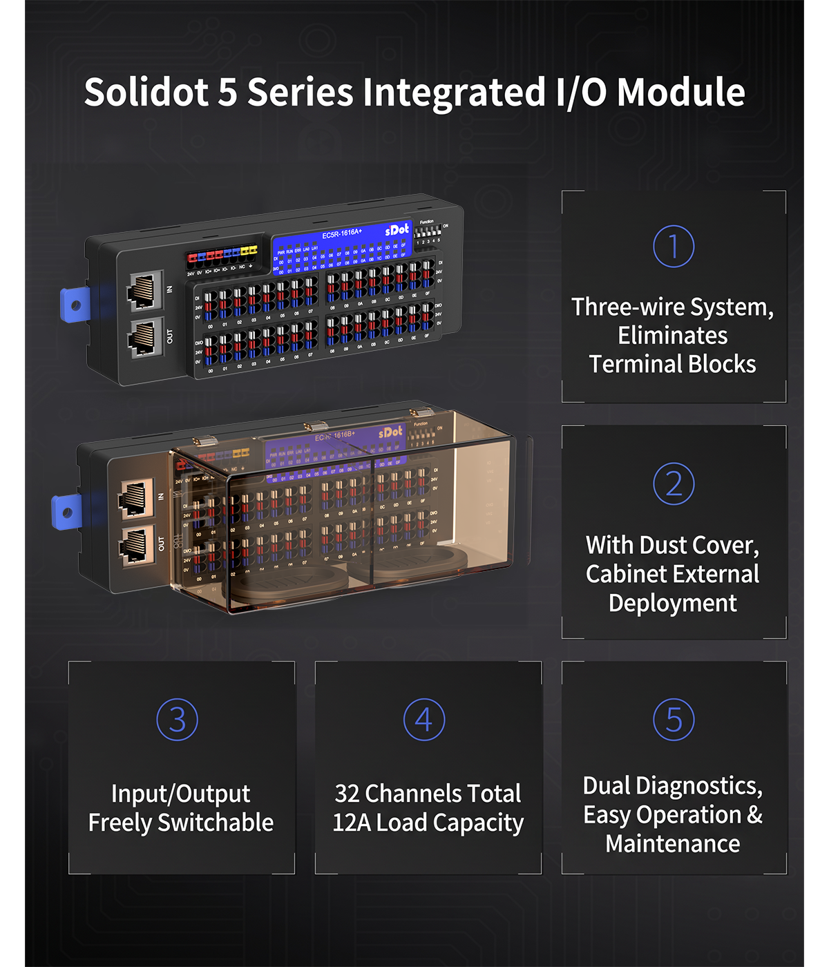
Module Introduction
Model | Description |
16-channel digital NPN input / 16-channel digital NPN input & output compatible module, 0.5 A | |
16-channel digital PNP input / 16-channel digital PNP input & output compatible module, 0.5 A |
Module wiring
The module uses an independent dual power supply design for the system side and the load side. During commissioning and on-site wiring, two sets of 24 V DC power supplies and the corresponding 0 V circuits must be connected separately—
· system-side power supply: supplies power to the module's internal communication chip and logic circuit
· Load-side power supply: provides the operating power for external loads on the DO output channels; the switching of the output channels is controlled by the internal logic.
The wiring characteristics of the two modules are as follows—
· EC5R-1616A+: the fixed DI ports only support connection of NPN type sensors; the module has an internal design that connects field 24 V and field 0 V.
· EC5R-1616B+: the fixed DI ports only support connection of PNP type sensors; the module has an internal design that connects field 24 V and field 0 V.
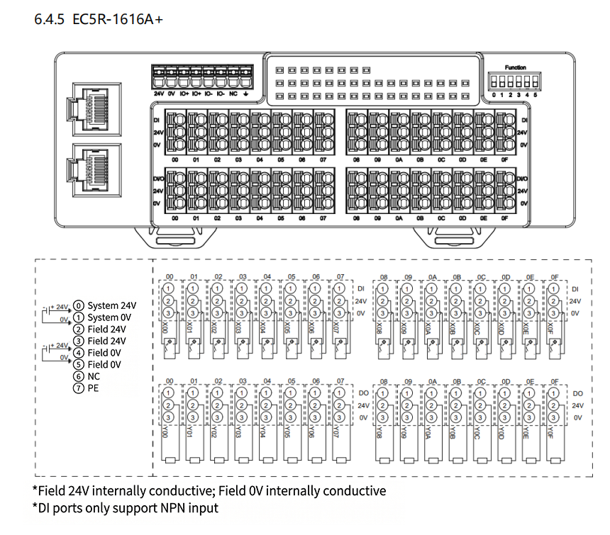
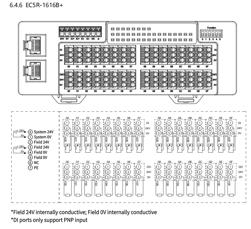
⚠️ The system power supply and the load power supply must be wired separately and independently. Mixed or common connection is prohibited. Otherwise, the module may experience communication errors, or the output channels may be damaged.
DIP Switch Definition
The module is equipped with a binary DIP switch for setting the module operating mode, the DI/DO channel configuration mode, and the input/output attributes of the compatible channels. Setting the DIP switch to the ON side corresponds to logic value 1, and setting it to the FF side corresponds to logic value 0. The DIP switch diagram is drawn for the 32-channel module; for the 16-channel module, the valid DIP switch positions are positions 0 to 3.
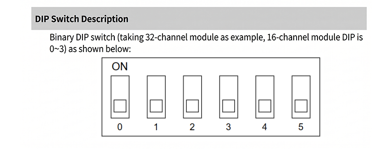
DIP switch position | DIP switch state | Function description |
No. 0 DIP switch
| 0 (OFF) | Default mode; the module's upstream telegram does not carry diagnostic information |
1 (ON) | Alarm mode; the module's upstream PDO data contains fault diagnostic codes, allowing the module's operational state to be read in real time | |
No. 1 DIP switch
| 0 (OFF) | The DI/DO property of the compatible channels is set by hardware via DIP switches 2 to 5 (this mode is recommended for routine use on site) |
1 (ON) | The DI/DO property of the compatible channels is automatically detected and adapted based on the module wiring |
When DIP switch 1 is set to 0, the DI/DO attributes of the 4 groups of compatible channels can be set individually via DIP switches 2 to 5. Each group corresponds to 4 channels, as defined below:
Configurable DI/DO DIP Switch setting table (effective when binary DIP switch 1 is set to 0) | |
DIP switch 2 setting (binary) | 0: Channels 00 ... 03 are output DO |
1: Channels 00 ... 03 are input DI | |
DIP switch 3 setting (binary) | 0: Channels 04 ... 07 are output DO |
1: Channels 04 ... 07 are input DI | |
DIP switch 4 setting (binary) | 0: Channels 08 ... 0B are output DO |
1: Channels 08 ... 0B are input DI | |
DIP switch 5 setting (binary) | 0: Channels 0C ... 0F are output DO |
1: Channels 0C ... 0F are input DI | |
⚠️ After changing the setting of any DIP switch, a complete power-off restart of the module must be performed for the new configuration parameters to take effect. If the DIP switches are adjusted while communication is running, the module operating mode will not be updated.
Configuration Selection and PDO data Area
Because the module supports alarm mode switching and the compatible channels support flexible DI/DO configuration, the PDO process data of the module is divided into multiple independent data areas. During configuration, the software settings must match the hardware DIP switch states.
1. Configuration Selection Matching Rules
Depending on the setting of DIP switch 0, the module is divided into the default mode and the alarm mode. In the EtherCAT Master project, the device model selected must be consistent with the hardware state—
· DIP switch 0 set to 0 (default version): select EC5R-1616A+ / EC5R-1616B+ for configuration
· DIP switch 0 set to 1 (alarm version): select the EC5R-1616A+-alarm / EC5R-1616B+-alarm configuration
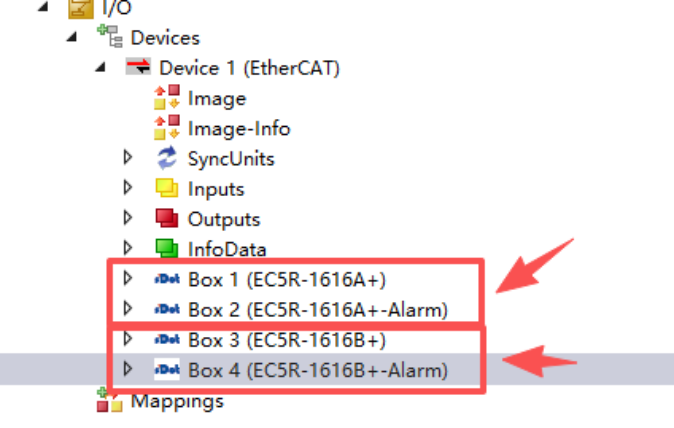
⚠️ If the configured model does not match the actual hardware DIP switch mode, PDO data mapping will be misaligned or even cause a communication error.
2. PDO data area in default mode
Taking EC5R-1616A+ as an example, when DIP switch 0 is set to 0, the PDO process data is divided into 3 independent areas:
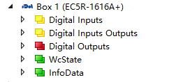
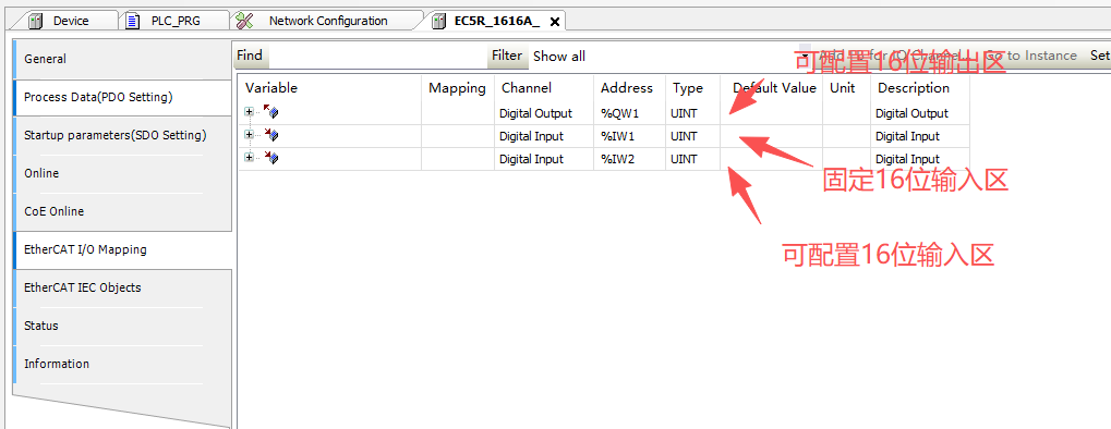
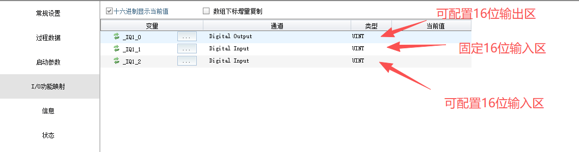
· digital Inputs (fixed 16-bit input area): corresponds to the first 16 hardware-fixed DI channels of the module; this is a read-only data area that reports the on/off status of the input channels in real time.
· digital Inputs Outputs (compatible channel input data area): corresponds to the channels configured as DI mode among the 16 compatible channels; their status data is synchronized to this read-only area.
· digital Outputs (compatible channel output data area): corresponds to the channels configured as DO mode among the 16 compatible channels; the master writes output control commands to this write-only area to switch the channels on and off.
3. PDO data area in alarm mode
When DIP switch 0 is set to 1, in addition to the 3 data areas of the default mode, a Diagnosis information (fault diagnosis information area) is added to upload module fault diagnosis codes, enabling the master to monitor the module's operating health in real time.
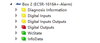
Alarm codes are reported in the module's upstream data. Common error codes and their meanings are as follows:
Error Code | Meaning |
0 x 0000 | No fault |
0 x 0001 | Load-side Voltage Not Connected |
0 x 0002 | DO output error |
0 x 0004 | Firmware does not match the current module model |
0 x 0008 | Firmware Upgrade Error |
0 x 0010 | Parameter Setting Error |
0 x 0020 | When the DI channel auto-adaptation bit is set to 1, the DO control address corresponding to this channel may be erroneously set to 1 |
PDO address mapping on mainstream PLC platforms
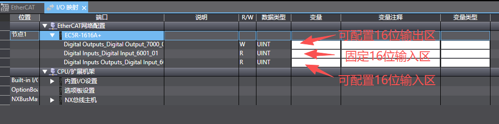
EtherCAT Master software from different brands differs in interface and variable naming, but the module's PDO partitioning logic and data structure are fully consistent, all comprising the three core areas: fixed input area, compatible channel input area, and compatible channel output area. Alarm mode adds an additional diagnostic information segment. The mapping on each mainstream platform is shown below (taking EC5R-1616A+ as an example):
Omron platform —
CODESYS platform —
Inovance AutoShop platform —
Keyence platform —
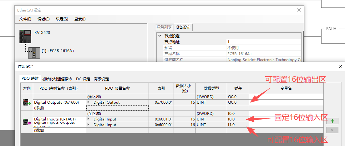
⚠️ In addition to the different address representations, the PDO entries themselves also carry index identifiers. Taking the Keyence platform screenshot as an example, digital Outputs corresponds to index 0 x 1600, mapped to 0 x 7000:01; Digital Inputs corresponds to 0 x 1A01, mapped to 0 x 6001:01; and digital Inputs Outputs corresponds to 0 x 1A02, mapped to 0 x 6002:01. When configuring address mapping, you can distinguish fixed input data from compatible channel data by the PDO entry name and index, avoiding writing output commands into the input data area, which would cause the I/O function to fail.