Knowledge

At a Glance
1. Demo Products
2. Configuration Tool
IOConfigTool
3. Communication mode
XB6S-C01SP configured as a Modbus RTU master
4. Demo slave
Modbus slave serial debugging software (read/write with function codes 03/06)
5. Key operations
Set the serial communication parameters → configure the Modbus command code for each node → download the configuration → read/write and determine status via the upstream/downstream addresses
6. Key Notes
The serial parameters of the master and slave must match exactly; for slave devices that respond slowly, extend the response timeout and polling delay appropriately
XB6S-EI2002 is a Solidot EtherNet/IP slice coupler, and XB6S-C01SP is a serial Communication module. When used together, XB6S-EI2002 handles EtherNet/IP communication with the PLC, while XB6S-C01SP handles the Modbus RTU master function on the serial side — that is, after configuration is completed in IOConfigTool, XB6S-C01SP acts as the master and actively reads from and writes to third-party Modbus RTU slave devices. So how exactly do you set the serial communication parameters, configure the Modbus command for each node, and use the host computer's downstream and upstream addresses to perform read/write control and determine communication status?
The overall configuration consists of four steps: define the slave read/write requirements → set the serial communication parameters in the host computer → enter the Modbus command code for each node and download it → implement read/write operations and status monitoring via the downstream and upstream addresses. This article uses the Modbus slave serial debugging software, which supports the Modbus RTU protocol, as the demo slave, and reads 2 registers with function code 03 and writes 2 registers with function code 06, fully demonstrating the entire configuration process.
Demo slave description
In this example, the Modbus slave serial debugging software, which supports the Modbus RTU protocol, is used as the slave for the case configuration:
· function code 03: read 2 registers
· function code 10: write 2 registers
Configuring serial communication parameters on the host computer
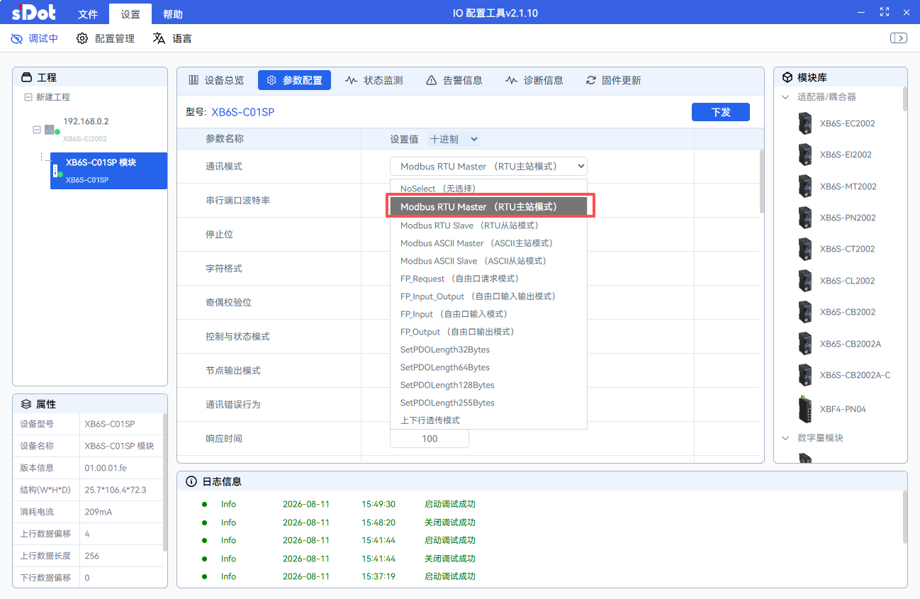
1. Setting the communication mode to Modbus RTU master
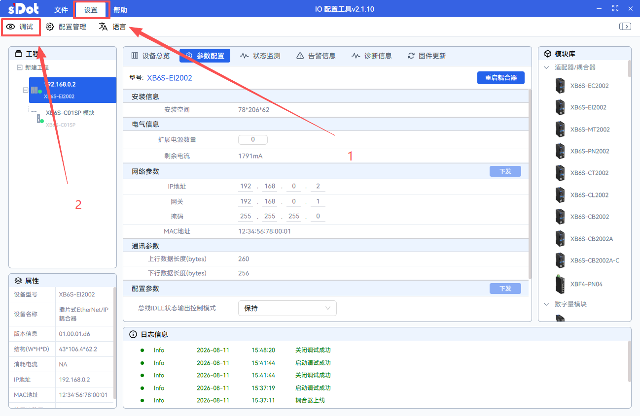
After the module is scanned by the host software, click "Settings" > "Debug" to enter debug mode, then select the XB6S-C01SP module, click "Parameter Configuration" > "Communication Mode", and set the communication mode to "Modbus RTU master".
2. Matching serial port parameters
Set the baud rate, stop bit, character format and parity mode according to the serial port parameters of the slave device, and make sure the master and slave configurations are exactly the same.
3. Setting control word parameters
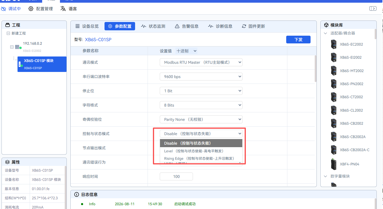
If the control word is to be enabled, it is recommended to select "High level trigger" as the control mode, and set the response timeout to 200 ms and the polling delay to 100 ms for higher communication stability.
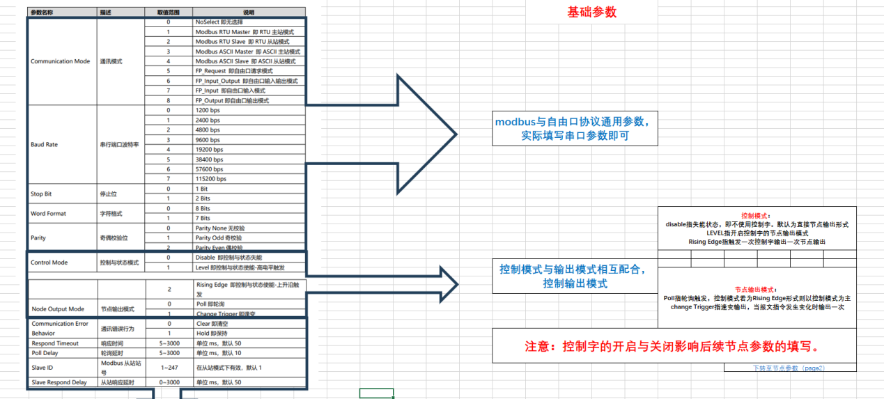
Note: With the default parameters, polling is relatively fast, and some slave devices that respond slowly may fail to respond in time and report an error. Appropriately extending the response timeout and polling delay can effectively improve communication stability.
4. Frame interval
In general, keep the default frame interval of 1.5T. If communication between the serial debugging assistant and the module is normal, and communication between the serial debugging assistant and the slave device is also normal, but communication between the module and the slave device fails, try gradually increasing the frame interval and test again.
Node parameter configuration
When the communication mode is Modbus RTU master and the control word is enabled, enter the parameters node by node according to the following rules. After configuration is complete, click "Download" to download the parameters to the coupler. This example configures 2 commands (function codes 03 and 06) and uses nodes 1 to 3 in total.
Node | Parameter | Entered value | Corresponding command description |
Node 1 | Parameter 1 | 2 (two nodes used in this example) | — |
Node 1 | Parameter 2 | 0 (default) | — |
Node 2 | Parameter 1 | 770 (0 x 00000302) | Function code 03, read 2 registers, start address 0 x 0 |
Node 2 | Parameter 2 | 1 (slave Station number) | — |
Node 3 | Parameter 1 | 525826 (0 x 00080602) | Function code 10 writes 2 registers, start address 0 x 8 |
Node 3 | Parameter 2 | 1 (slave Station number) | — |
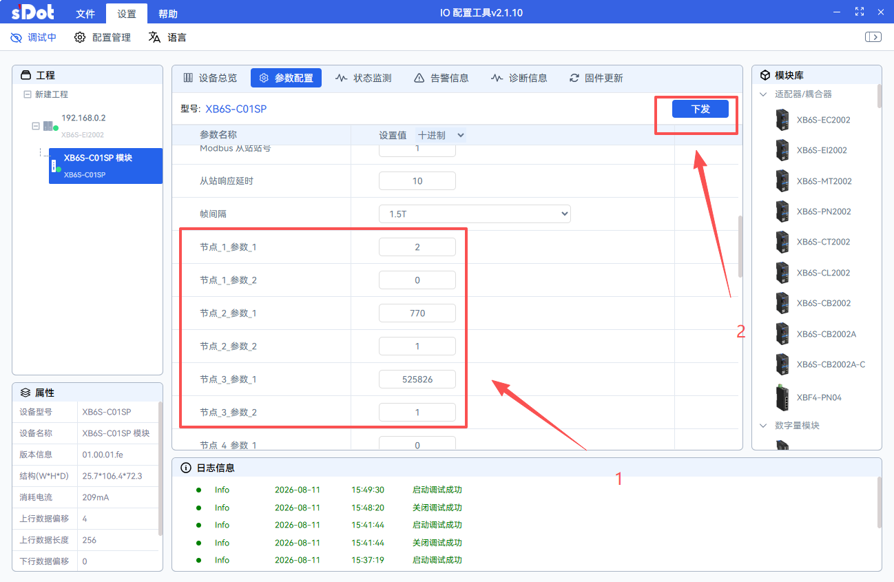
Note: For node 1, parameter 1 is the number of nodes actually used in this case (nodes 2 to 3, 2 nodes in total). Starting from node 2, each node corresponds to one Modbus command, and parameter 1 is in hexadecimal format.
Address read/write and communication status judgment
1. Read/write operations
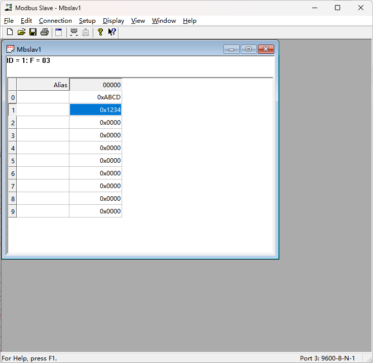
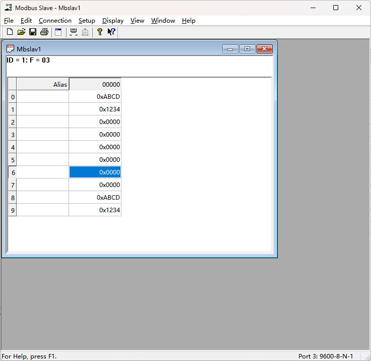
Taking the example of reading 2 holding registers starting from address 0000 of slave address 01 via function code 03, simulate the slave in Modbus slave. The configuration result is as follows:
After configuration is complete, send control commands via the downstream address on the host computer and read the status via the upstream address. In this example, all addresses start from 0:
Upstream data (32 bytes) | |||
byte number | Function | Meaning | Address range |
1 | status word | Bit0: Idle state | 1 byte |
Bit1: Busy state, i.e. data transmission in progress | |||
Bit2: Completion state, i.e. data transmission complete | |||
2 | alarm code | See alarm code | 1 byte |
3 | Input Data | Serial Communication module input data | the last 30 bytes |
4 | Input Data | ||
… | … | ||
32 | Input Data | ||
Downstream data (32 bytes) | |||
byte number | Function | Meaning | Address range |
1 | control word | When the configuration parameters control mode is level, set to 1 to send data | 1 byte |
When the configuration parameters control mode is Rising Edge, 0- > 1 sends data | |||
2 | Output Data | Serial Communication module output data | the last 31 bytes |
3 | Output Data | ||
… | … | ||
32 | Output Data | ||
note: The process data in the above table configures one node in level or Rising Edge mode. If two nodes are configured, byte numbers 1 and 2 of the upstream data are the status bit and alarm code of node 1, byte numbers 3 and 4 are the status bit and alarm code of node 2, and the remaining bytes are data bits; byte number 1 of the downstream data is the control bit of node 1, byte number 2 is the control bit of node 2, and the remaining bytes are data bits. A maximum of 15 nodes can be configured.
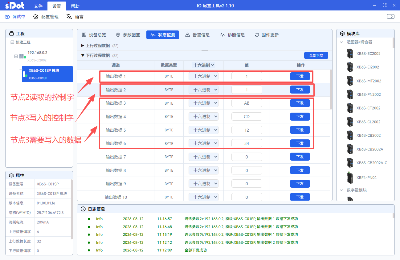
In the downstream data, enable node 2 and node 3 respectively. After writing the data to be sent to node 3, click Send:
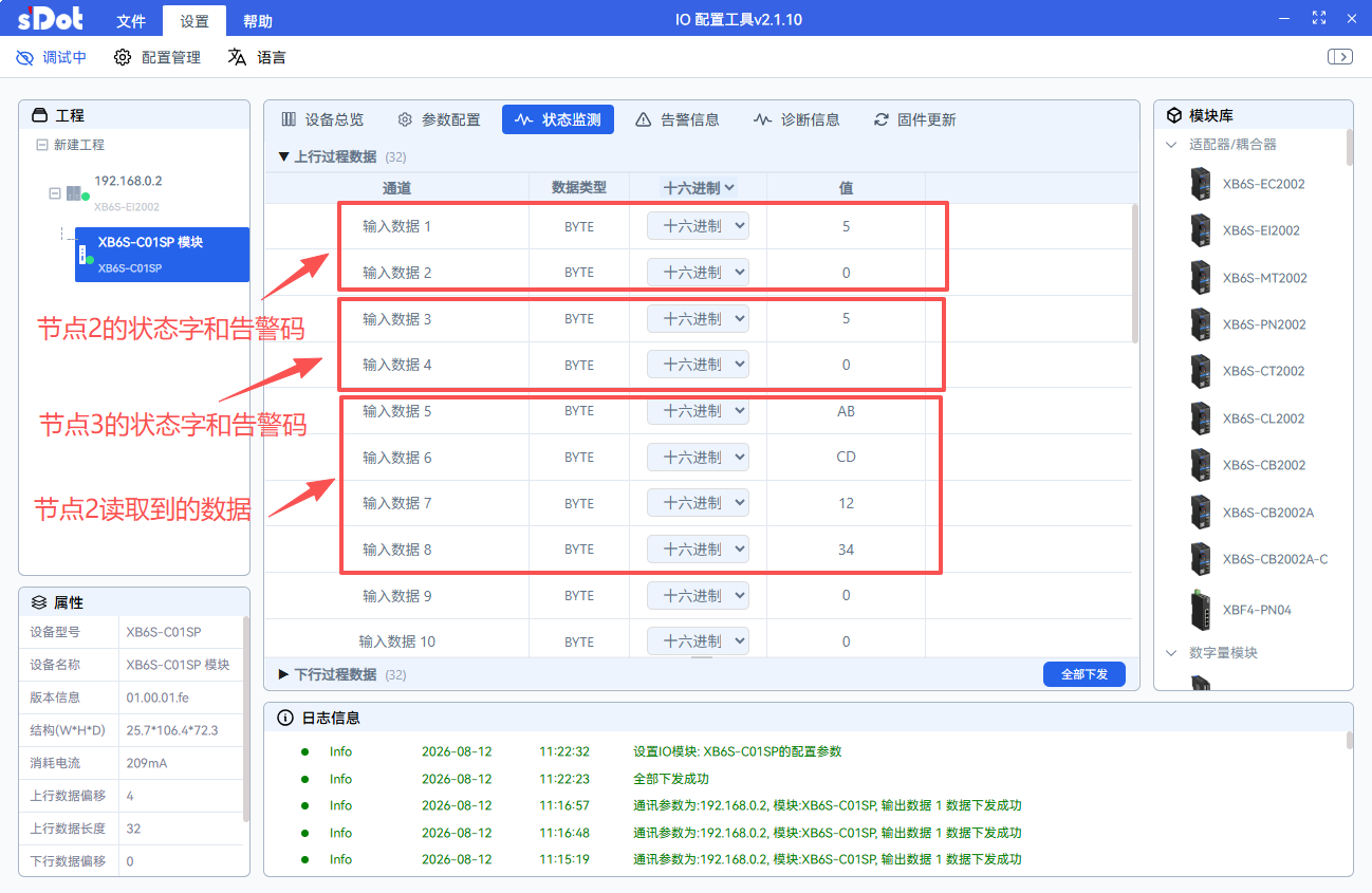
In the upstream data of the host computer, the status word and alarm code of the corresponding configured node can be seen. At the same time, the values of two registers were read from address 0000 of the Modbus slave, and the values of two registers were written to address 0008:
2. Determining the communication status
During normal communication, the status word changes continuously (typically toggling between 2 and 5), and the alarm code remains 0. If a communication error occurs, check the alarm code to locate the problem.
fault code | Note |
0 x 00 | No error |
0 x 01 | Slave device address error |
0 x 02 | Function code error |
0 x 03 | CRC check error |
0 x 04 | Response byte count error |
0 x 05 | Coil register data error |
0 x 06 | Holding register data error |
0 x 07 | Illegal data address |
0 x 08 | Slave device fault |
0 x 09 | LRC check error |
0 x 0C | Data length error |
0 x 0D | Data conversion error |
0 x 0E | ASCII frame error |
0 x 0F | Response timeout |