Knowledge

The Solidot IO-Link IOL7 series includes two versions, IOL7A and IOL7B. IOL7A uses a metal housing, IOL7B a plastic housing, and both have protection rating IP67. Both versions offer an IO-Link Master, a 16-channel digital hub (input/output/configurable) and an 8-channel analog module (voltage/current input/output Compatible) with identical functions, so you only need to choose according to the on-site application environment.
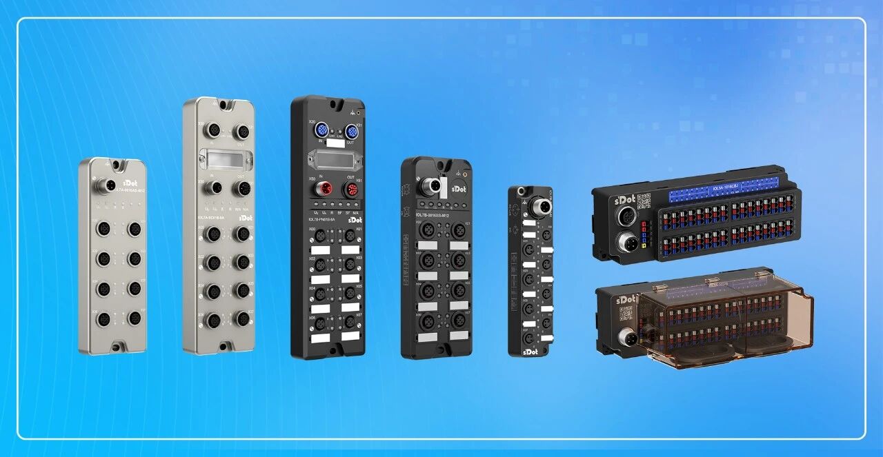
IO-Link Series product overview
The configurable items of the entire series are handled through two entry points:
The master's own parameters are configured in the master module parameters, including port mode, output behavior on communication loss, and the pin2 overcurrent recovery method;
Hub parameters are sent by the master via ISDU, writing the corresponding value by index.
The two systems differ in when configuration takes place: an EtherCAT Master can read and write ISDU online while running, whereas a PROFINET master must complete the writing during the configuration phase. The following sections describe each in turn—
The master's own parameters are set in the master module parameters
1. Port mode
Each port can be set to IO-Link mode or standard DI/DO mode. When used as an ordinary digital channel, pin4 and pin2 are each set to standard DI or standard DO, with standard DI as the default; when an IO-Link Device is connected, set the corresponding port to IO-Link mode and leave the other ports at their defaults. Beyond mode selection there are no additional parameters.
2. Output on communication disconnection
When a bus fault occurs, the port output can be configured as output 0, output 1, or hold last output value. This is set independently for each port, and selected according to the requirements of each process section for the output signal in the fault state.
3. Pin 2 overcurrent recovery
After overcurrent occurs on pin 2, the recovery mode can be configured as automatic Recovery or manual Recovery; the default is automatic Recovery.
The above three items are all set in the master module parameters. In an EtherCAT environment, TwinCAT3 is used as an example; in a PROFINET environment, TIA Portal V17 is used as an example. They can be completed in the master device parameters and online parameter area. For specific interface steps, refer to the configuration application chapter of the corresponding master manual.
II. Downloading HUB parameters via ISDU
Each configuration item of the HUB corresponds to a set of ISDU parameters. On the master side, simply enter the index, subindex, length, and data in sequence to write them.
For an EtherCAT Master, operate in the ISDU parameter area of TwinCAT3: first leave control empty, enter the four data items, then select write. An error code of 0 indicates a successful write; a read operation can then be performed to verify. After configuration is complete, reload the device for it to take effect. For a PROFINET master, enter the ISDU parameters during the configuration phase in TIA Portal V17. The index, subindex, and length are expressed in decimal, there is no control item, and the download is completed when the configuration is downloaded. HUB parameters support power-off retention.
[example 1: Hub channel direction]
Taking IOL7A-16CB-M12 as an example, all 16 channels are inputs by default. Configure it so that the first 8 channels are inputs and the last 8 channels are outputs: Index 0 x 0042, subindex 0 x 00, length 2, data 00FF.
[example 2: Changing an analog channel to output]
All 8 channels of the IOL7A-A8C-M12 are analog inputs by default. Change channel 0 to analog output: Index 0 x 0040, subindex 0 x 01, length 1, data 01. The other channels remain at their defaults.
When HUB parameters need to be reset, this can be done via a system command, for example Restore Factory settings: Index 0 x 0002, subindex 0, length 1, data 0 x 82. Configuration items such as the hub's input conversion, short-circuit recovery, and input filter, and the analog module's measuring range and output preset value, have their value definitions in the parameter chapter of each HUB user manual. Simply write them as described above.
III. Configuration quick reference
Configuration content | Configuration entry | Example setting value |
Port Mode | Master Module Parameter | Default standard DI; Select IO-Link mode when connecting an IO-Link Device |
When communication is interrupted Port output | Master Module Parameter | Output 0/output 1/Retain last state, per port |
Pin2 overcurrent recovery | Master Module Parameter | Automatic (default) or manual |
Hub Channel direction | ISDU Download | Index: 0 x 0042 subindex: 0; Length: 2; |
Hub Input Filter | ISDU Download | Index: 0 x 0049; Subindex: 0 x 01; (0 x 01-0x10 correspond to the 16 DI channels respectively) Length: 1; Data: 0 x 19 (subindex 0 x 01-0x10 correspond to the 16 DI channels respectively; the value 01 corresponds to channel X00-pin4; Data 0 x 19 corresponds to 25, filtering range 0 ... 25, 0 means off, 1 = 2 ms, 2 ms x 25 = 50 ms) |
Analog channel Input/output | ISDU Download | Index: 0 x 0040 subindex: 1; Length: 1; Data: 0 x 01 (channel 0 changed to output) |
Analog measuring range | ISDU Download | Index: 0 x 0041 subindex: 1; Length: 1; Data: 0 x 01, (subindex 0 x 01 corresponds to channel X00; Data 0 x 01 corresponds to 0 ... 10 V) |
Restore Factory settings | ISDU Download | Index: 0 x 0002 subindex: 0; Length: 1 Data: 0 x 82 |
The above is an introduction to the parameter configuration methods for the Solidot IO-Link IOL7A/B series. If you have any questions, you are welcome to contact us. We will be glad to serve you!