Knowledge


Quick overview
1. Applicable Products
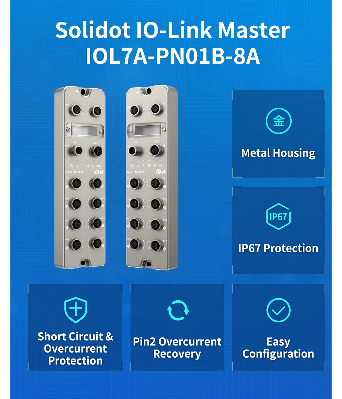
IOL7A-PN01B-8A, PROFINET fieldbus, 8x class-A port IO-Link Master, IP67, metal housing
2. Panel Structure
Fieldbus interfaces X30/X31, power connectors X50/X51, 8 I/O interfaces X00 ... X07, system indicator group and network indicator
3. Fieldbus interface
2x M12-D, 4-pin, female connector (socket), 100 Mbps, station-to-station distance <= 100 m
4. Power connector
2x M12-L, 5-pin, male connector (pin) & female connector (socket), 24 V DC (18 V ... 30 V), US and UA total current each Max: 9 A
5. I/O interface
8x M12-A, 5-pin, female connector (socket), input and output signal types are both PNP
6. Key wiring Points
US and UA are each supplied by a separate Switching power supply; Pin5 connects to PE; unused connectors must be fitted with waterproof caps.
7. Mounting and Fixing
M5 x 22 mm or larger screws; one mounting hole each at the top and bottom of the module.
I. Product Structure
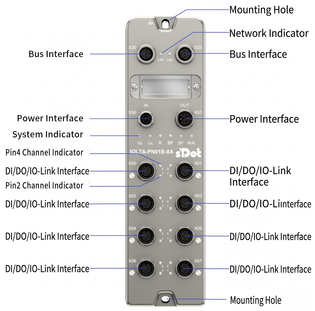
The layout of each part of the panel corresponds one-to-one with the silk-screen markings, identified from top to bottom as follows:
· Mounting holes: one each at the top and bottom of the module; use M5 x 22 mm or larger screws to fix the body to the equipment or bracket.
· Fieldbus interface: two connectors at the top, X30 (IN) and X31 (OUT), M12-D; between the two connectors are the network indicators L/A1 and L/A2, corresponding to the IN and OUT directions respectively.
· power connector: X50 (IN) and X51 (OUT) in the middle, M12-L; male connector (pin) and female connector (socket) are used as a pair.
· system Indicator group: located below the power connector, with silk-screen markings in the order US, UA, R, BF, SF, N/A.
· I/O interface: 8 connectors X00 ... X07 at the bottom, M12-A, arranged in two columns and four rows; the 0 and 1 marked next to each connector are channel indicators, 0 corresponding to pin4 and 1 to pin2.
II. Indicator LED function
The panel indicators are divided into three categories: the system Indicator group, network indicators and channel indicators. The system Indicator group reflects the power supply and Operational state, the network indicators reflect the link and data status of the two fieldbus ports, and the channel indicators are located directly beside the I/O interface and reflect the input/output and IO-Link communication status of each channel.
1. System and network indicators
Name | Label | Color | State | State description |
System power indicator | US | Green/Red | Steady green | Power Supply Normal |
Flashing red | System power supply greater than 11 V and less than 18 V | |||
Off | Product not powered on or power supply fault | |||
Auxiliary power indicator | UA | Green/Red | Steady green | Power Supply Normal |
Flashing red | Auxiliary power supply greater than 11 V and less than 18 V | |||
Steady red | Auxiliary power supply not powered on or voltage less than 11 V | |||
Off | Product not powered on or power supply fault | |||
Run Status Indicator | R | Green | Steady On | System running normally |
Off | Operating fault | |||
Bus Fault LED | BF | Red | Steady On | No network connection |
Flashing | No PROFINET connection established to the controller | |||
Off | PROFINET connection established to the controller | |||
System error indicator | SF | Red | Steady On | Fault in the PROFINET master system |
Off | PROFINET master system operating normally or not powered on | |||
Network indicator IN | L/A1 | Orange | Steady On | Connection established |
Off | Connection disconnected | |||
Green | Flashing | Network connection established | ||
Steady On | Network connection with data exchange | |||
Off | No data exchange or fault | |||
Network indicator OUT | L/A2 | Orange | Steady On | Connection established |
Off | Disconnected | |||
Green | Flashing | Network connection established | ||
Steady On | Network connection with data exchange | |||
Off | No data exchange or fault |
2. Channel indicators
Name | Label | Color | Status | Status description |
Pin 4 Channel indicator | 0 | Yellow Red Green | Steady yellow | Pin 4 input or output status is 1 |
Steady red | Pin 4 overcurrent | |||
Flashing red | IO-Link error | |||
Steady On in green | IO-Link communication connection established | |||
Flashing in green | IO-Link communication not connected | |||
Off | Pin 4 input or output status is 0 | |||
Pin2 Channel indicator | 1 | Yellow Red | Steady yellow | Pin2 input or output state is 1 |
Steady red | Pin2 overcurrent | |||
Flashing red | Pin1 overcurrent (LED1 and LED0 flash simultaneously) | |||
Off | Pin2 input or output state is 0 |
III. Bus interface Definition
The Fieldbus interface is an M12-D female connector (socket) with 4 pins. X30 and X31 have identical definitions, differing only in the in/out direction; distinguish them by the silk-screen markings on the panel when wiring.
Pin | Function |
1 | TX+, Transmit Data+ |
2 | RX+, Receive Data+ |
3 | TX-, Transmit data- |
4 | RX-, Receive data- |
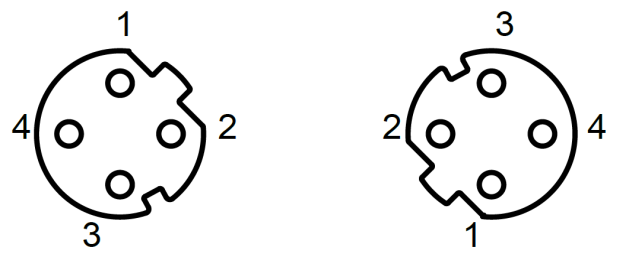
Bus interface connection view (M12-D, female connector (socket))
Pin1 and pin2 are the positive terminals for transmission and reception, and pin3 and pin4 are the corresponding negative terminals. The transmission rate on the fieldbus side is 100 Mbps. Use Category 5 or higher UTP/STP cable as the data transmission medium; STP is recommended.
IV. Power interface Definition
The power connector is M12-L with 5 pins, and the male connector (pin) is used together with the female connector (socket). X50 is the power input and X51 is the power output; both have the same definition.
Pin | Function | Wire color |
1 | +24 V US | Brown |
2 | 0 V GNDA | White |
3 | 0 V GNDS | Blue |
4 | +24 V UA | Black |
5 | PE | Grey |
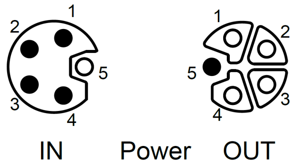
Power interface connection view (M12-L, male connector (pin) and female connector (socket)):
IN end and OUT end
Pin1 and pin3 are the positive and negative terminals of the system power supply US, pin4 and pin2 are the positive and negative terminals of the Auxiliary power supply UA, and pin5 is PE. The supply range is 24 V DC (18 V ... 30 V), with Reverse Polarity Protection. The module's own US current Consumption is no greater than 100 mA, and the UA current Consumption is 0 mA, i.e. UA supplies power only to the I/O load and the pin2 output; the UA total current and US total current are each limited to 9 A.
V. I/O interface Definition
The I/O interface is an M12-A female connector (socket) with 5 pins; the 8 ports X00 ... X07 have the same definition.
Pin | Function | Wire color |
1 | +24 V US | Brown |
2 | DI/DO | White |
3 | 0 V GNDS | Blue |
4 | DI/DO/IO-Link | Black |
5 | PE | Gray |
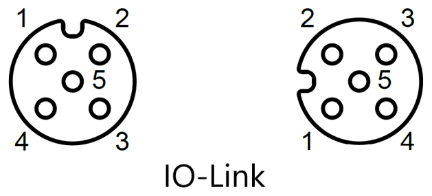
I/O interface connection view (M12-A, female connector (socket)):
Pin1 ... Pin5
Pin1 and pin3 are taken from the system power supply US and provide the Operating power supply for the connected sensors and actuators; Pin2 is fixed as DI/DO; Pin4 supports three modes: DI/DO/IO-Link, and the specific mode is determined by the configuration parameters.
Note:
*The power supply for pin1 and pin3 comes from the system supply US, and the power supply for the pin4 signal output is also provided by US.
*The power supply for pin2 comes from UA. If the class-A port does not use the pin2 output function, UA can be left unconnected.
Both the input and output signal types are PNP, with a maximum of 16 input channels and 16 output channels each. The maximum output current per channel is 0.5 A for pin4, 2 A for pin2 and 2 A for pin1, and the total output current is a maximum of 9 A each for US and UA. Pin4 and pin2 have Short circuit overcurrent protection in DO mode, and pin2 supports automatic Recovery and manual Recovery.
VI. Wiring guide
1. Power interface wiring diagram
X50 is the power input connector, wired according to the pin numbers: Pin1 connects to +24 V of the system power supply US, pin3 connects to 0 V of US; Pin4 connects to +24 V of the Auxiliary power supply UA, pin2 connects to 0 V of UA; Pin5 connects to PE.
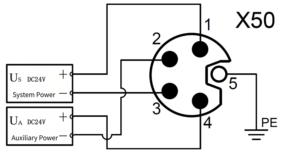
Power interface wiring diagram:
Pin1/pin3 connect to the system power supply US
Pin4/pin2 connect to the Auxiliary power supply UA, pin5 connects to PE
Note:
*It is recommended to supply the system power and auxiliary power from separate switching power supplies to ensure stable operation.
2. I/O interface wiring diagram
The I/O interface has two wiring methods depending on the connected device, input and output; the signal type is PNP in both cases.
The left side shows PNP input wiring, supporting 3-wire and 2-wire sensors. Pin1 is +24 V, pin3 is 0 V, pin2 (DIB) and pin4 (DIA) are two signal inputs, and pin5 connects to PE. For 3-wire sensors, power and signal are connected separately; for 2-wire sensors, only signal and 0 V are connected.
The right side shows PNP output wiring: one end of the load connects to pin2 (DOB) or pin4 (DOA), and the other end connects to 0 V at pin3; in this wiring method pin1 is not connected, and pin5 connects to PE.
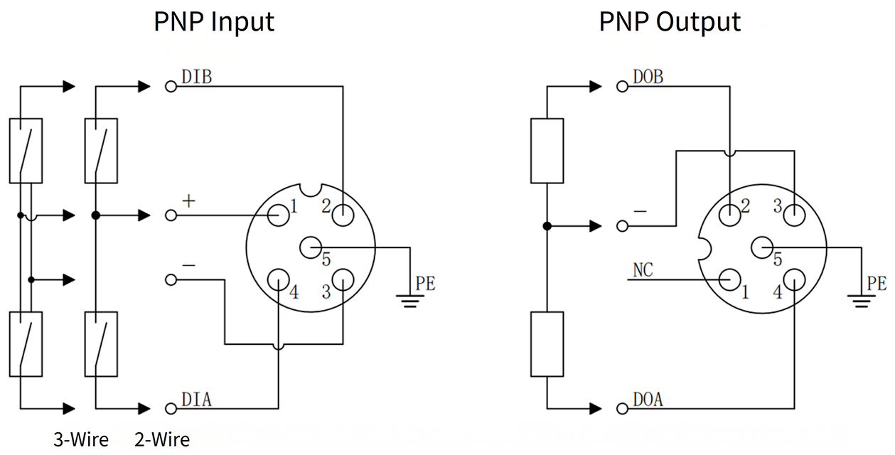
I/O interface wiring diagram:
Left side: PNP input (3-wire and 2-wire)
Right side: PNP output
Note:
*Unused connector interfaces must be fitted with the waterproof caps supplied with the module and tightened to avoid compromising the IP67 protection rating.