Knowledge

Quick overview
1. Demo Products
XB6S-EI2002 + XB6S-3200 + XB6S-0032A
2. Supporting Platform
Inovance Easy-523 PLC + AutoShop V4.11
3. Communication protocol
EtherNet/IP
4. Configuration Workflow
Create a new project → PLC communication → Import EDS file → module configuration → Configure upstream/downstream bytes → download → Monitor I/O addresses
5. Key Notes
After importing the EDS file, AutoShop must be restarted manually; module parameters can only be modified via IOConfigTool
How do I configure the Solidot Slice I/O EtherNet/IP Coupler XB6S-EI2002 in AutoShop?
This document uses an Easy-523 PLC with the XB6S-EI2002, XB6S-3200 and XB6S-0032A as an example, and, using AutoShop V4.11, describes the complete workflow for importing an EDS file, module configuration, upstream/downstream byte configuration, program download and I/O address monitoring.
1. Creating a new project
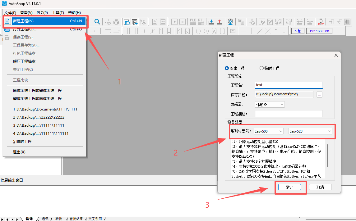
Create a new project in AutoShop and select the PLC model that matches the actual hardware.
2. Establishing the PLC communication connection
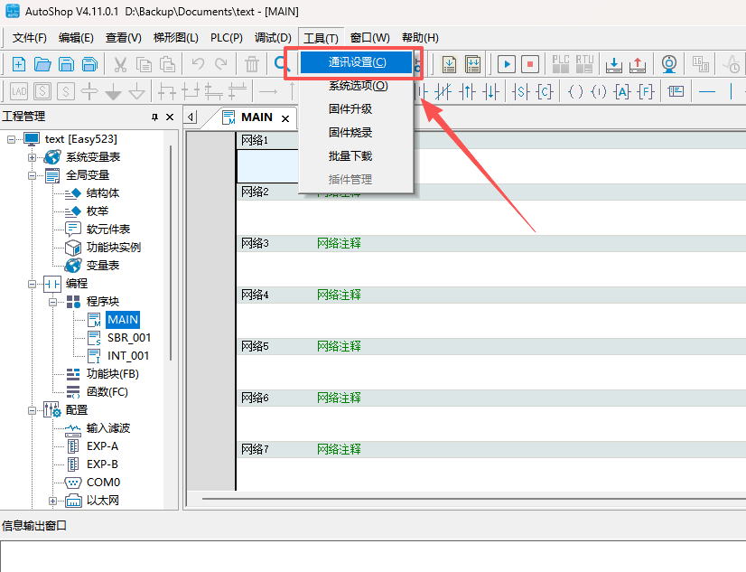
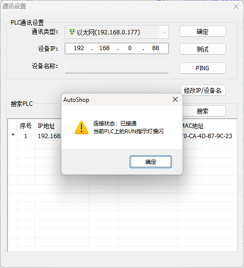
Click "Tools" → "Communication Configuration" in the menu bar, and establish a connection to the PLC in the Communication configuration window.
3. Importing the EDS file for XB6S-EI2002
In the toolbox on the right, right-click "EtherNet/IP Devices" and select "Import Device EDS". In the dialog that opens, browse to the folder containing the EDS file, select the corresponding file and click "Open" to complete the import.
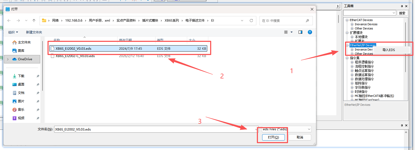
Note: After the EDS file has been imported successfully, AutoShop must be restarted manually; only then can the newly imported device be used for configuration.
4. Module configuration
1. Automatic scan (recommended)
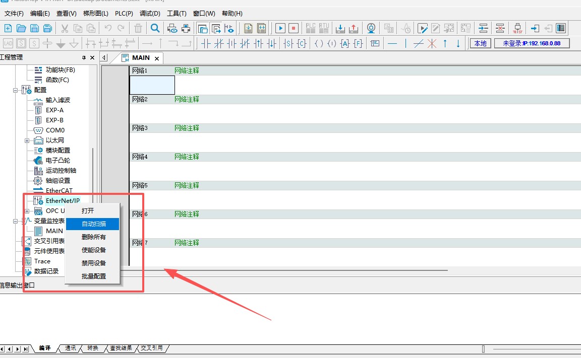
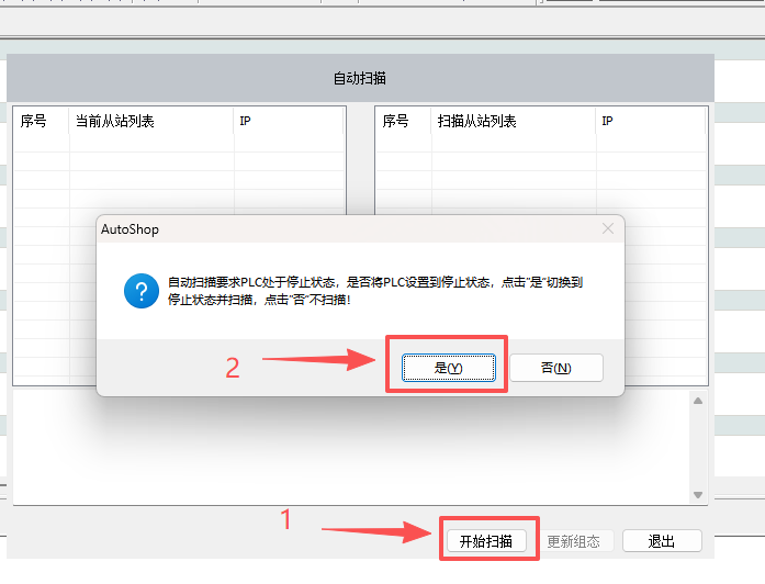
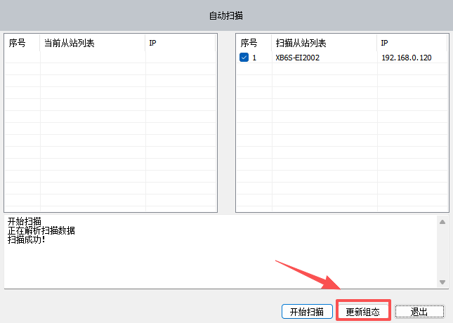
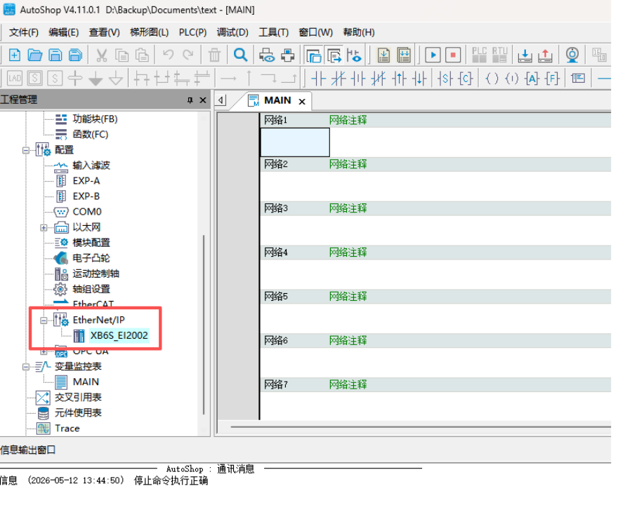
In the "EtherNet/IP Settings" window, right-click the "EtherNet/IP" icon and select "Automatic Scan". In the scan window, click "Start Scan". After confirming, wait for the scan to complete, then click "Update Configuration" to automatically add the modules properly connected in the network to the configuration.
2. Manual addition of modules
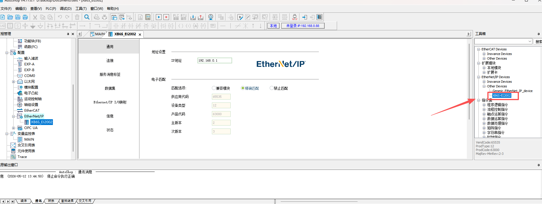
In the toolbox on the right side of the "EtherNet/IP Settings" window, expand "EtherNet/IP Devices", locate XB6S-EI2002, and double-click it to add it to the configuration.
3. Configuring the upstream and downstream byte lengths
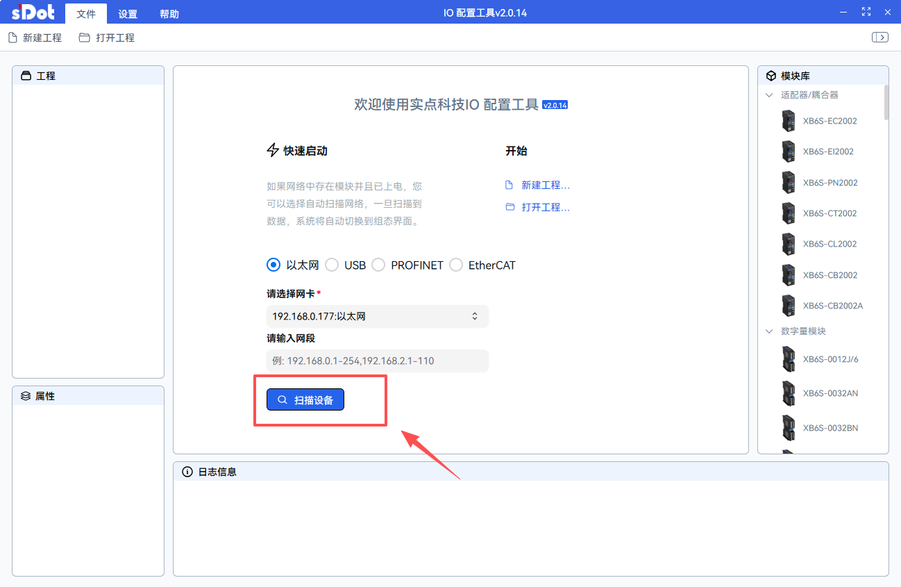
Use the IO configuration Tool (IOConfigTool) provided on the Solidot official website to scan the coupler and confirm the upstream (input) and downstream (output) byte lengths of the modules currently connected to the coupler.
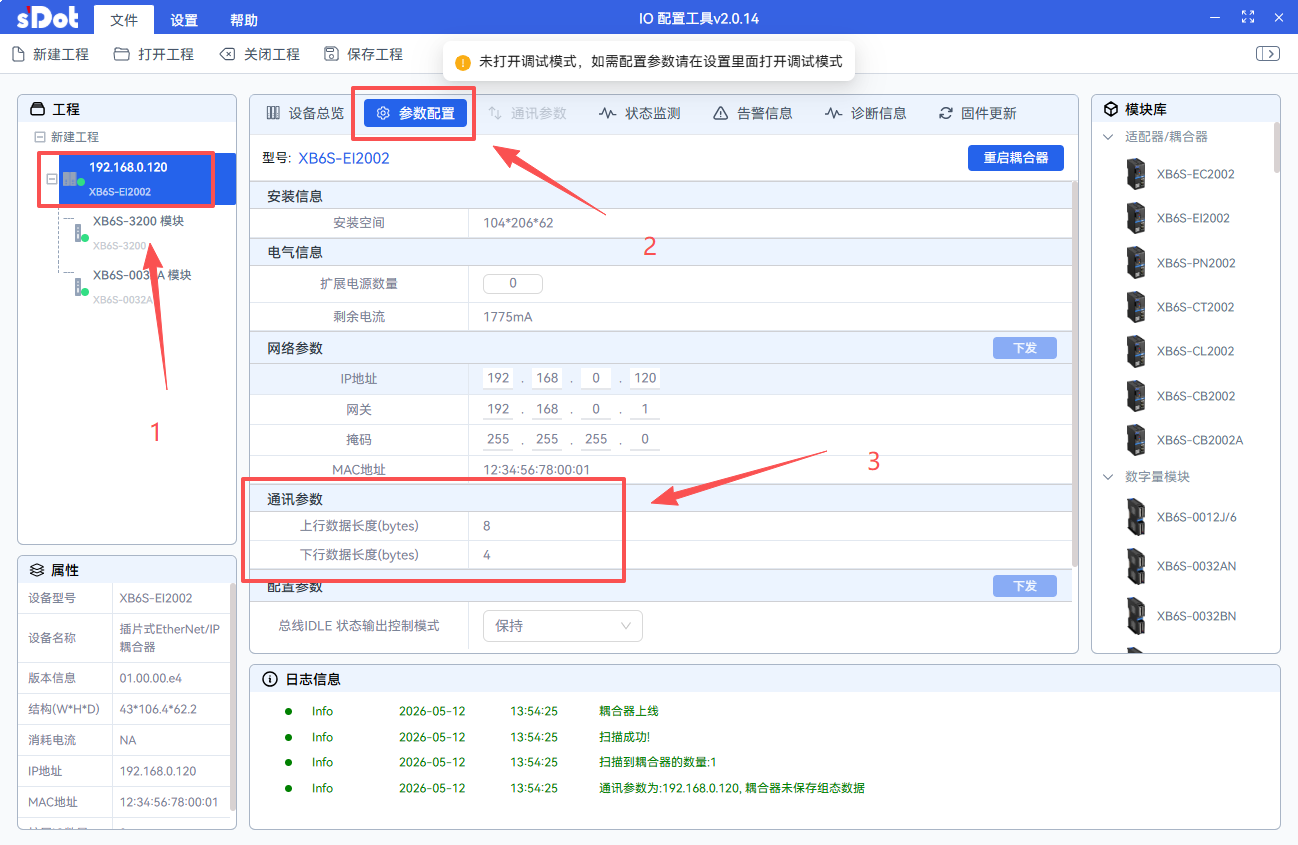
After obtaining the byte lengths, set them in the coupler's connection configuration according to the actual upstream and downstream byte lengths to ensure consistency with the coupler's actual data frame length.
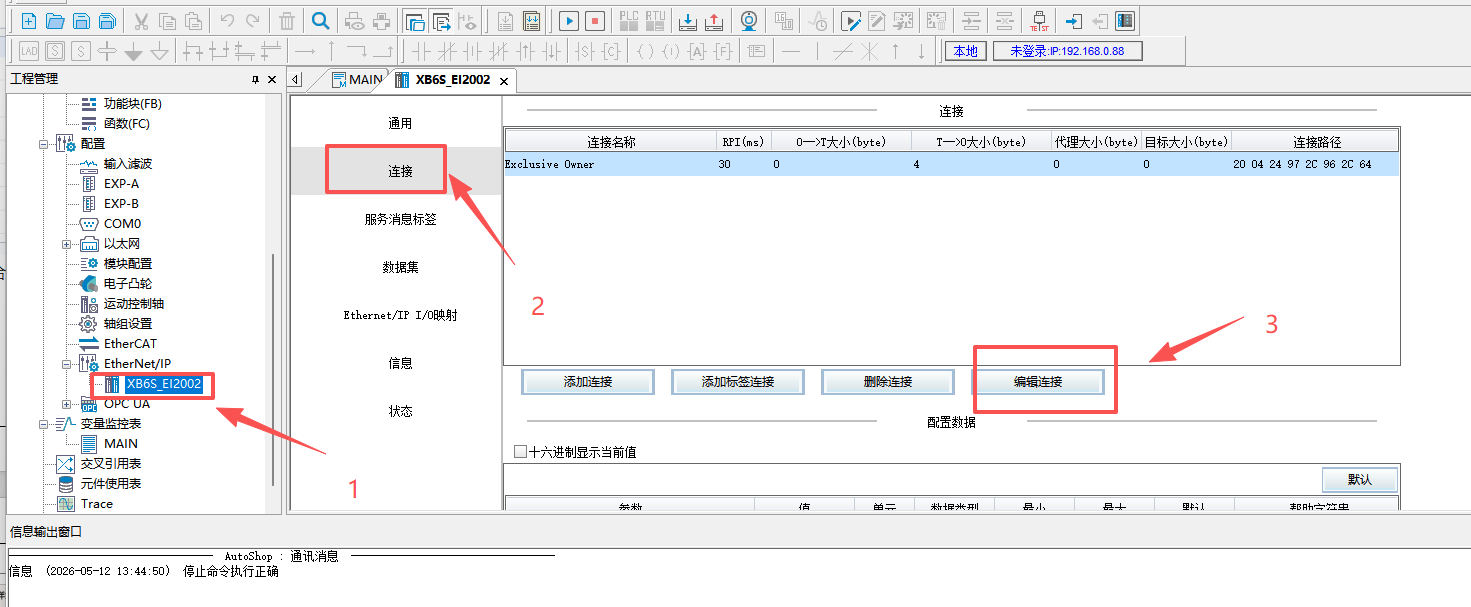
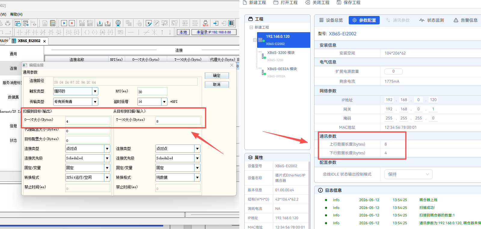
Note: The upstream and downstream byte lengths must match the total data volume of the modules actually mounted on the coupler. If the configuration is inconsistent, data offset or communication errors may occur.
4. Configuration download
Click "PLC" → "Download" → "OK" and wait for the download to complete. After the download is complete, power-cycle the PLC and the coupler.

5. I/O address monitoring and use
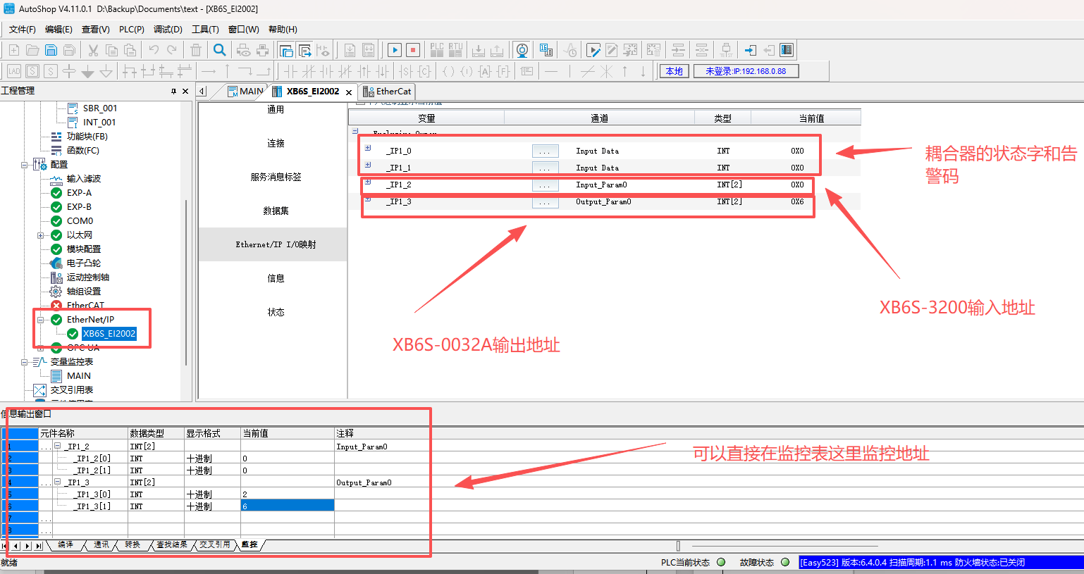
Once communication is established, the program can directly read or control via the global variables mapped to the corresponding addresses.
6. Module parameter settings
The parameters of XB6S-EI2002 can only be modified using the IO configuration Tool IOConfigTool provided on the Solidot official website; direct modification within the AutoShop software is not supported.
5. Notes
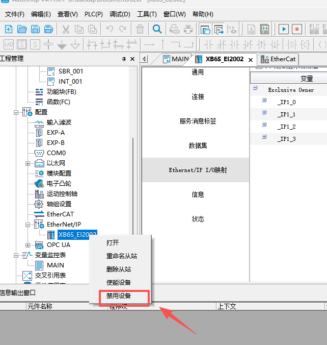
In "EtherNet/IP Settings", if a device is set to "Disabled", AutoShop will not perform EtherNet/IP communication with that device. Please ensure that all devices requiring communication are enabled.