XBF4-EC04 Complete Troubleshooting Guide
Article Overview
1. Applicable Product
XBF4-EC04+ Loaded I/O Modules
2. Problem Symptom
Coupler or I/O modules cannot establish EtherCAT communication
3. Troubleshooting Dimensions
Physical link / Terminal resistor / DIP switch station address / Configuration / Power-up sequence / Power supply / Hardware failure / Electromagnetic interference
4. Troubleshooting Entry Point
First observe the LED status of the coupler and I/O modules, then refer to the quick LED index table in this article to locate the corresponding troubleshooting item
5. Total Troubleshooting Items
11 items covering all common fault scenarios from the physical layer to the configuration layer
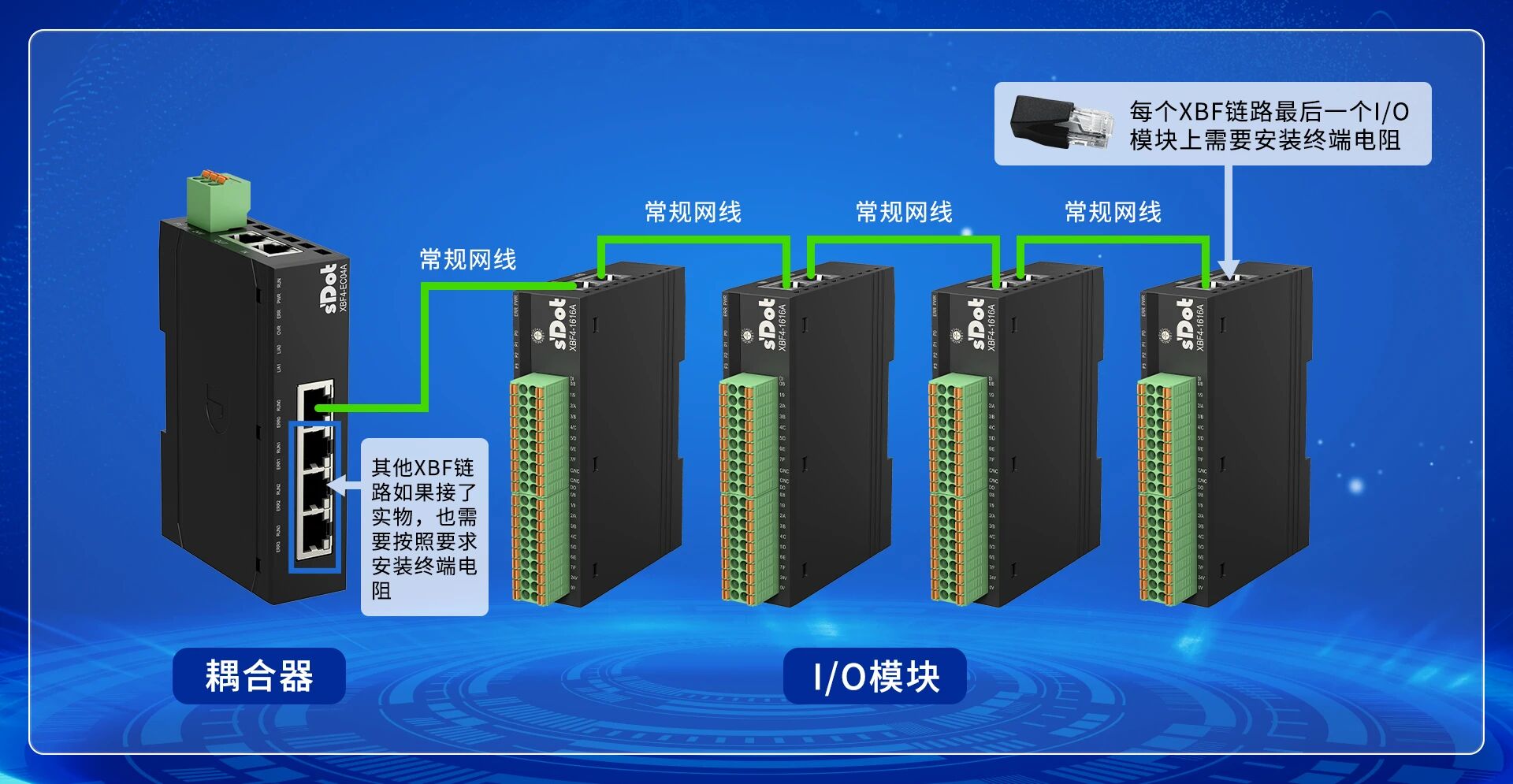
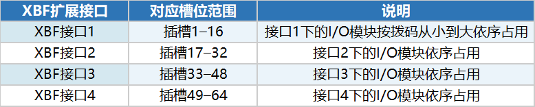
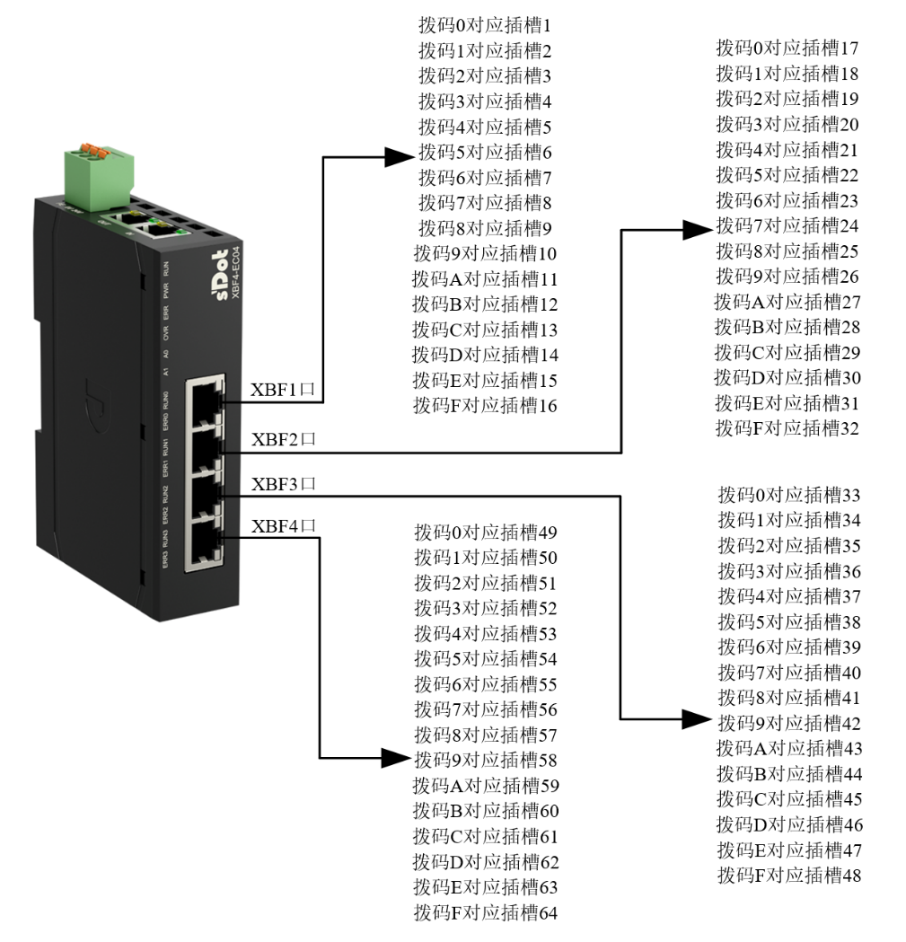
The XBF4-EC04 is a Solidot discrete I/O EtherCAT coupler. On the top of the module there are two RJ45 EtherCAT ports for communication with the EtherCAT master controller. On the front there are four RJ45 expansion ports, each of which can connect up to 16 discrete I/O modules in series (the modules have DIP switches for station addresses 0–F, addresses must be unique within the same link). The four ports can expand to a total of up to 32 discrete I/O modules.
When troubleshooting communication issues, it is recommended to first observe the LED status of the coupler and I/O modules, use the quick LED index table in this article to quickly locate the problem level, and then handle it step by step according to the corresponding troubleshooting items. This article compiles 11 common communication fault phenomena and solutions.
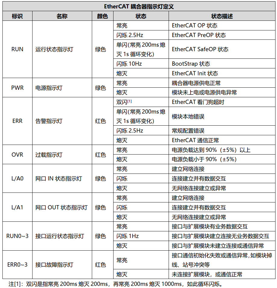
I.XBF4-EC04Discrete Coupler LED Indicator Diagram (image reference)
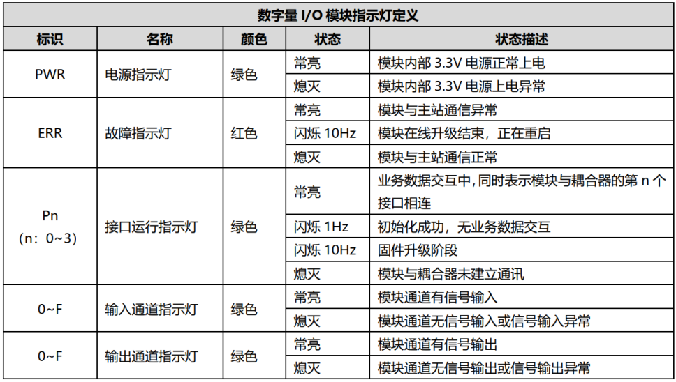
II. Discrete I/O Module LED Indicator Diagram (image reference)
III. Detailed Troubleshooting
Troubleshooting 1: EtherCAT Protocol Layer Physical Link Disconnection
Fault Phenomena:
● XBF4-EC04 L/A0 and L/A1 LEDs are both off.
Solutions:
● Check whether the network cable between XBF4-EC04 and the master is normal and whether the connectors are firmly inserted (Cat5e or better finished cables are recommended).
● Check whether the PLC and XBF4-EC04 Ethernet ports are used correctly, confirming the IN and OUT ports are not reversed.
● If the PLC software supports auto-scan, check whether XBF4-EC04 can be detected.
Troubleshooting 2: XBF Bus Layer Physical Link Disconnection
Fault Phenomena:
RUN n (n: 0–3) and ERR n (n: 0–3) LEDs are both off.
I/O module PWR, ERR, and Pn (n: 0–3) LEDs are all off.
Solutions:
●● Check whether the network cable between the I/O module and XBF4-EC04 is normal and whether the connectors are firmly inserted (Cat5e or better finished cables are recommended).
● Check the wire sequence of the RJ45 connectors at both ends. The sequence must be identical on both ends (straight-through cable); crossover is not required.
Troubleshooting 3: Terminal Resistor Not Installed
Fault Phenomena:
I/O module Pn (n: 0–3) LEDs flash or are off.
Solutions:
Check whether a terminal resistor is installed on the last I/O module at the end of the corresponding XBF link (the terminal resistor is shipped with the coupler by default).
For the C3 valve island, the terminal resistor is a separate accessory, model XBF-C3FD-ZDDZ.
Troubleshooting 4: I/O Module DIP Switch Station Address Conflict
Fault Phenomena:
● XBF4-EC04 RUN n LED off, ERR n LED steady on.
● I/O module PWR LED steady on, ERR and Pn LEDs off.
Solutions:
Check the DIP switch station addresses of all I/O modules under the same XBF link to confirm there are no duplicates (station addresses must be unique within each link).
Troubleshooting 5: Configuration Mismatch with Physical Modules or Incomplete Configuration
Fault Phenomena:
● XBF4-EC04 RUN n LED flashes, ERR n LED off.
●I/O module PWR LED steady on, ERR LED off, Pn LED flashes.
Solutions:
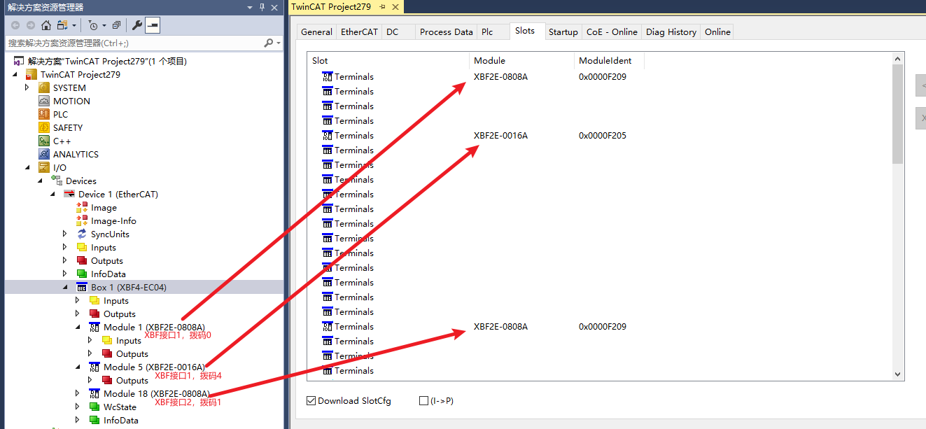
Check whether the module models and DIP switch addresses connected to the four XBF expansion ports are configured according to the slot rules.
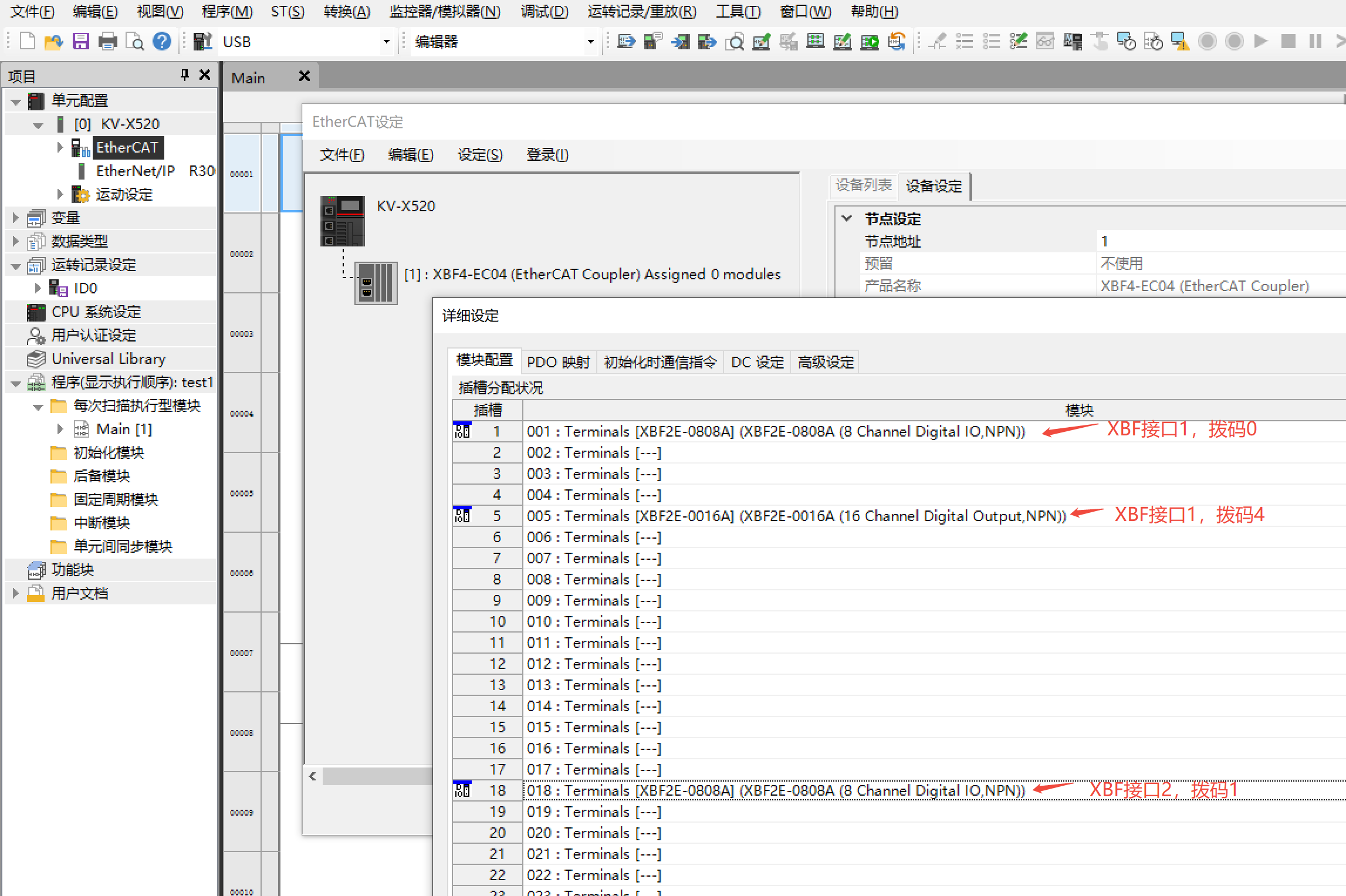
If the master supports auto-scan (e.g., TwinCAT3), simply click auto-scan to automatically complete the configuration without manual slot configuration.
Troubleshooting 6: Incorrect Operation Sequence — Coupler Powered On Before Connecting I/O Modules
Fault Phenomena:
● XBF4-EC04 RUN n and ERR n LEDs are both off.
● I/O module PWR LED steady on, ERR and Pn LEDs off.
Solutions:
● Correct power-up sequence: With XBF4-EC04 powered off, first complete: set I/O module DIP switches, install terminal resistors on the last I/O module of each XBF link, and connect I/O module cables to the coupler (these three steps have no priority order). Then power on XBF4-EC04.
● If the operation sequence is incorrect, power cycle theXBF4-EC04.
Troubleshooting 7: Power Supply Wiring Anomaly
Fault Phenomena:
● XBF4-EC04 PWR LED is off.
Solutions:
Power the module according to the correct wiring method and confirm the PWR LED lights up.
If the power supply rises in a stepped manner (unstable voltage), the module may not start properly. Re-power and ensure stable voltage.
Troubleshooting 8: XBF4-EC04 Hardware Failure
Fault Phenomena:
● After multiple power-ons, the PWR LED never lights up, and a multimeter confirms normal power.
● XBF4-EC04 has only PWR LED steady on; all other indicators are off.
● No I/O modules connected; after power cycling, ERR n LEDs remain steady on.
Solutions
●If the XBF4-EC04 is abnormal, it needs to be replaced.
●If the XBF4-EC04 is damaged, it needs to be replaced.
Troubleshooting 9: I/O Module Hardware Failure
Fault Phenomena:
After multiple power-ons, the I/O module PWR LED does not light up, while power and network cables are confirmed normal.
I/O module has only PWR LED steady on; ERR and Pn LEDs are both off.
Solutions:
If the I/O module is abnormal, it needs to be replaced.
If the I/O module is damaged, it needs to be replaced.
Troubleshooting 10: Master PLC Failure
Fault Phenomena:
The PLC cannot switch its current operating state, or bus alarms occur frequently.
Solutions:
Refer to the manual of the corresponding PLC model for self-check. For detailed information about the current state, consult the controller manufacturer.
Confirm that PLC resources are sufficient to avoid overloading more modules due to insufficient resources.
Troubleshooting 11: Strong Electromagnetic Interference Causing Disconnection or Communication Anomaly
Fault Phenomena:
● Packet loss on the bus communication.
● XBF4-EC04 RUN and ERR LEDs flash, triggering communication alarms.
【解决办法】
Solutions:
Interference sources are generally divided into two types: power side interference and communication side interference. Identify interference sources and optimize wiring, keeping away from sources such as high-power inverters, servo motors, and drives.
Add ferrite cores to the network cables to reduce interference.
Use shielded network cables whenever possible.
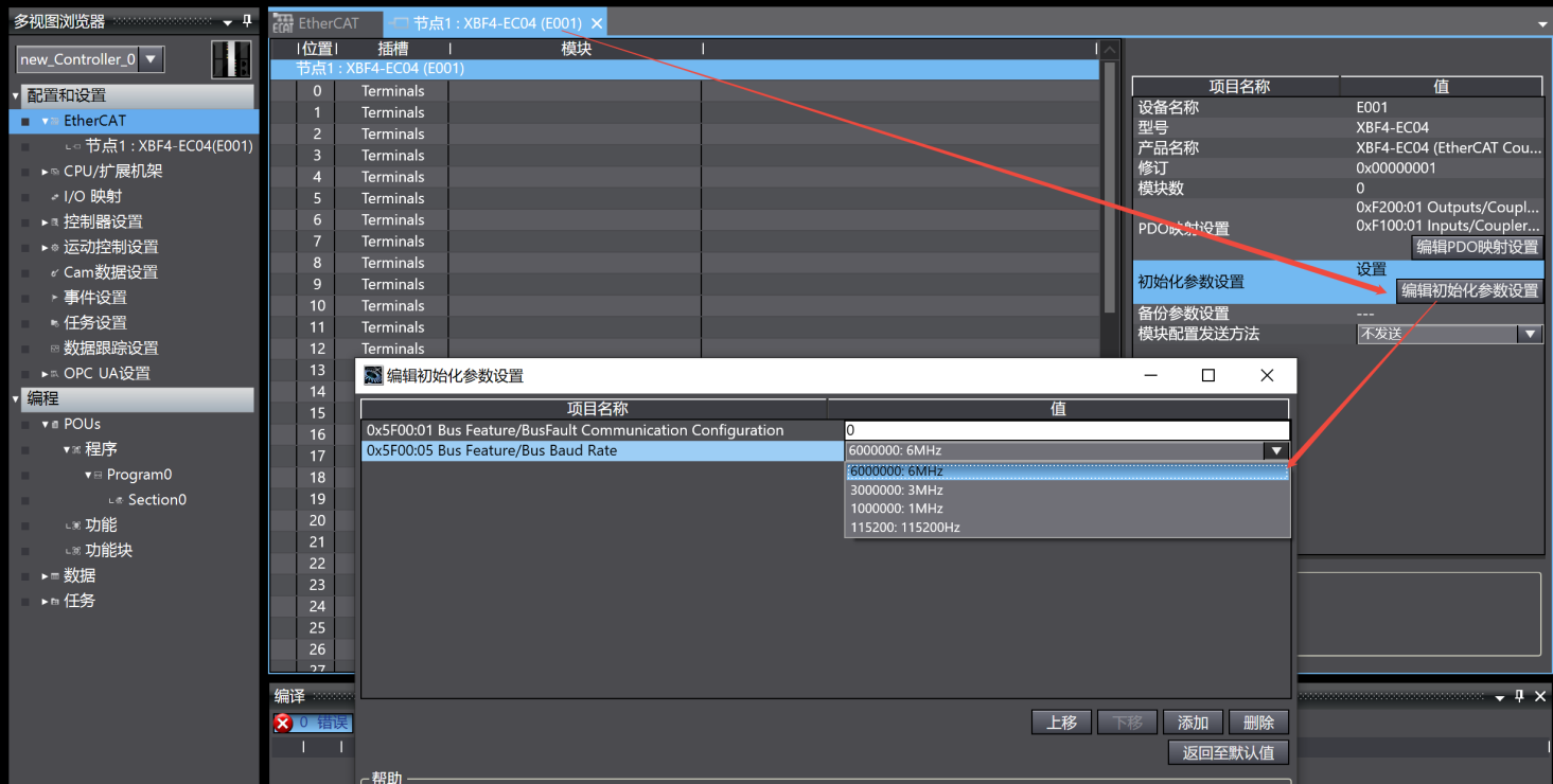
Reduce the baud rate of XBF4-EC04 (default maximum 6MHz; options: 3MHz, 1MHz, or 115200Hz).
Example — setting baud rate:
Edit initialization parameters: set index 5F00, subindex 05.