How to allocate addresses for discrete coupler XBF4-EC04A in Inovance AutoShop
Article Overview
1. Applicable Product
2. Platform
Inovance AutoShop (for Inovance H5U, Easy series PLC)
3. Core Content
Auto-scan and slot allocation rules, output/input address mapping rules, variable binding method
4. Key Point of Address Mapping
Slot numbers are assigned in ascending order; input area Module1~32 are diagnostic information, actual data starts after Module32
5. Prerequisite
The coupler has completed hardware configuration and normal EtherCAT communication is established
On the Inovance AutoShop platform, how are addresses allocated for the Solidot discrete EtherCAT protocol coupler XBF4-EC04A and its expansion modules? Understanding this rule is a prerequisite for correct variable binding and avoiding address confusion. AutoShop uses auto-scan to identify all modules behind the coupler, assigning slot numbers in the order of "discrete interface number from small to large, and within the same interface, DIP switch value from small to large". Address mapping strictly follows the principle of "slot number from small to large" in sequence.
This article takes a typical topology with 4 expansion interfaces and a total of 10 modules as an example to explain the complete operation methods of slot scanning, address mapping, and variable binding.
I. Preparation
Operations such as new project creation, importing configuration files, and topology configuration are not covered in this article. Please ensure the coupler has normal communication before proceeding.
II. Example Topology of This Article
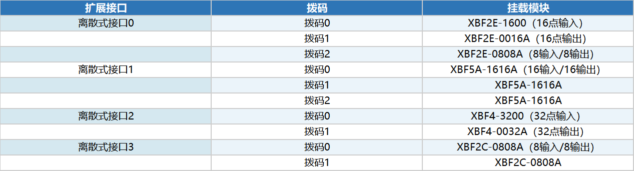
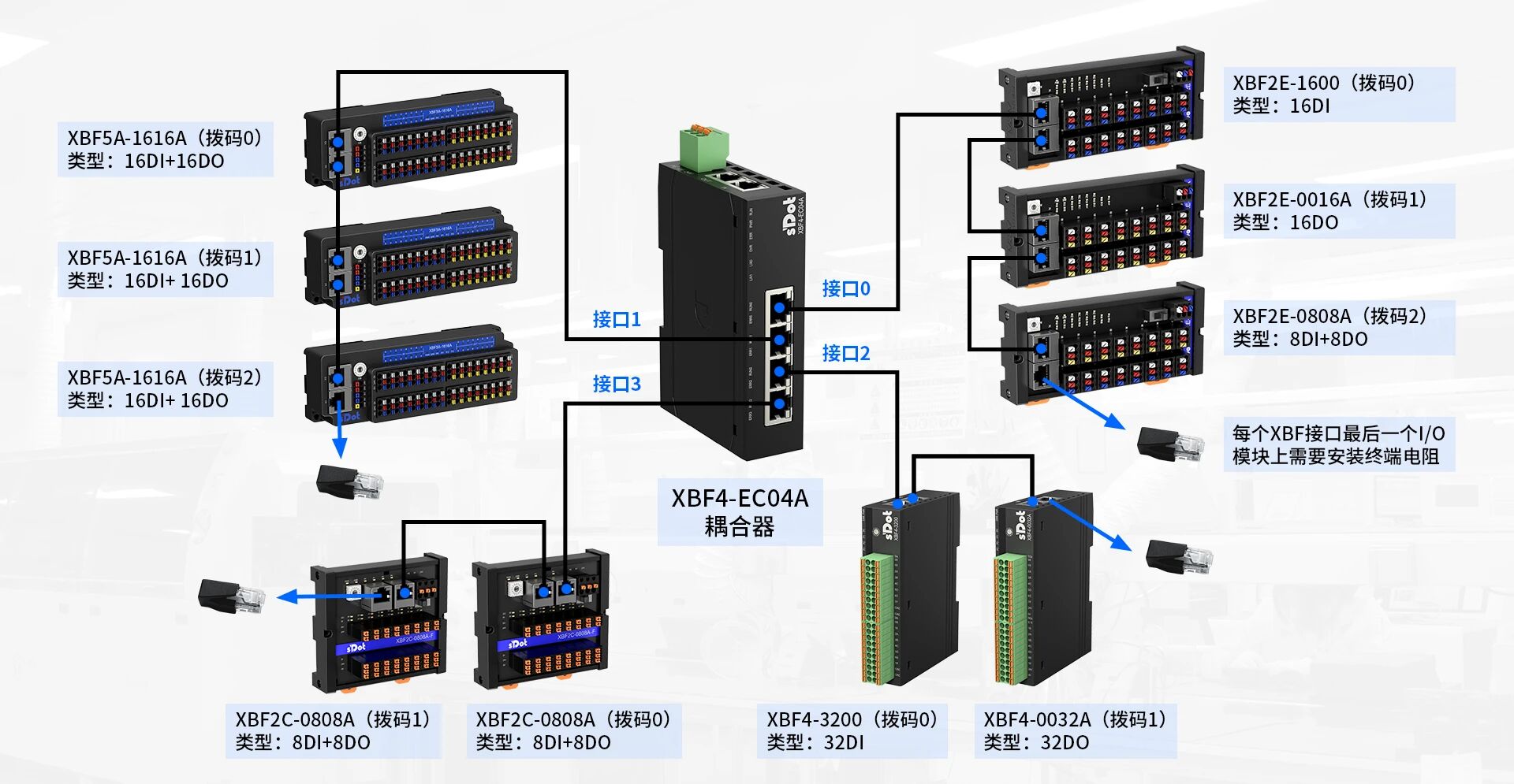
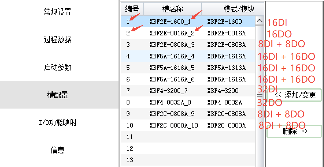
XBF4-EC04A provides 4 expansion interfaces (discrete interfaces 0–3). Each interface can have multiple modules, distinguished by DIP switch addresses. The example topology in this article covers various types including digital input/output and mixed modules, and is highly representative. Details are shown in the diagram.
III. AutoShop Auto-Scan and Slot Configuration
1. Auto-Scan Operation Steps
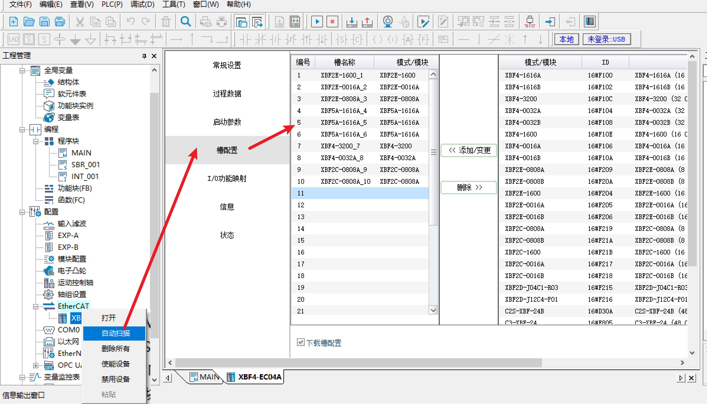
Right-click [EtherCAT] → [Auto Scan]. After scanning, all identified module models can be viewed in [Slot Configuration]. AutoShop supports automatic identification of all modules behind the coupler, avoiding tedious manual addition and configuration errors.
2. Scan Result Sorting Rules
Scan results are automatically sorted according to the following rules, with slot numbers increasing from 1:
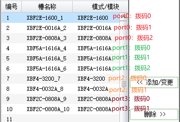
Sorted by discrete interface number from small to large: first interface 0, then interfaces 1, 2, 3.
Within the same interface, sorted by DIP switch value from small to large: DIP 0 first, then DIP 1, and so on.
四、地址分配规律解析
IV. Analysis of Address Allocation Rules
In [Slot Configuration], each module name has a number at the end (e.g., XBF2E-0016A_2). This number represents the slot number of the module on the bus. Slot numbers are automatically assigned by the software based on the scan order, starting from 1. The address mapping order strictly follows the principle of "slot number from small to large".
1. Output Address Mapping Description
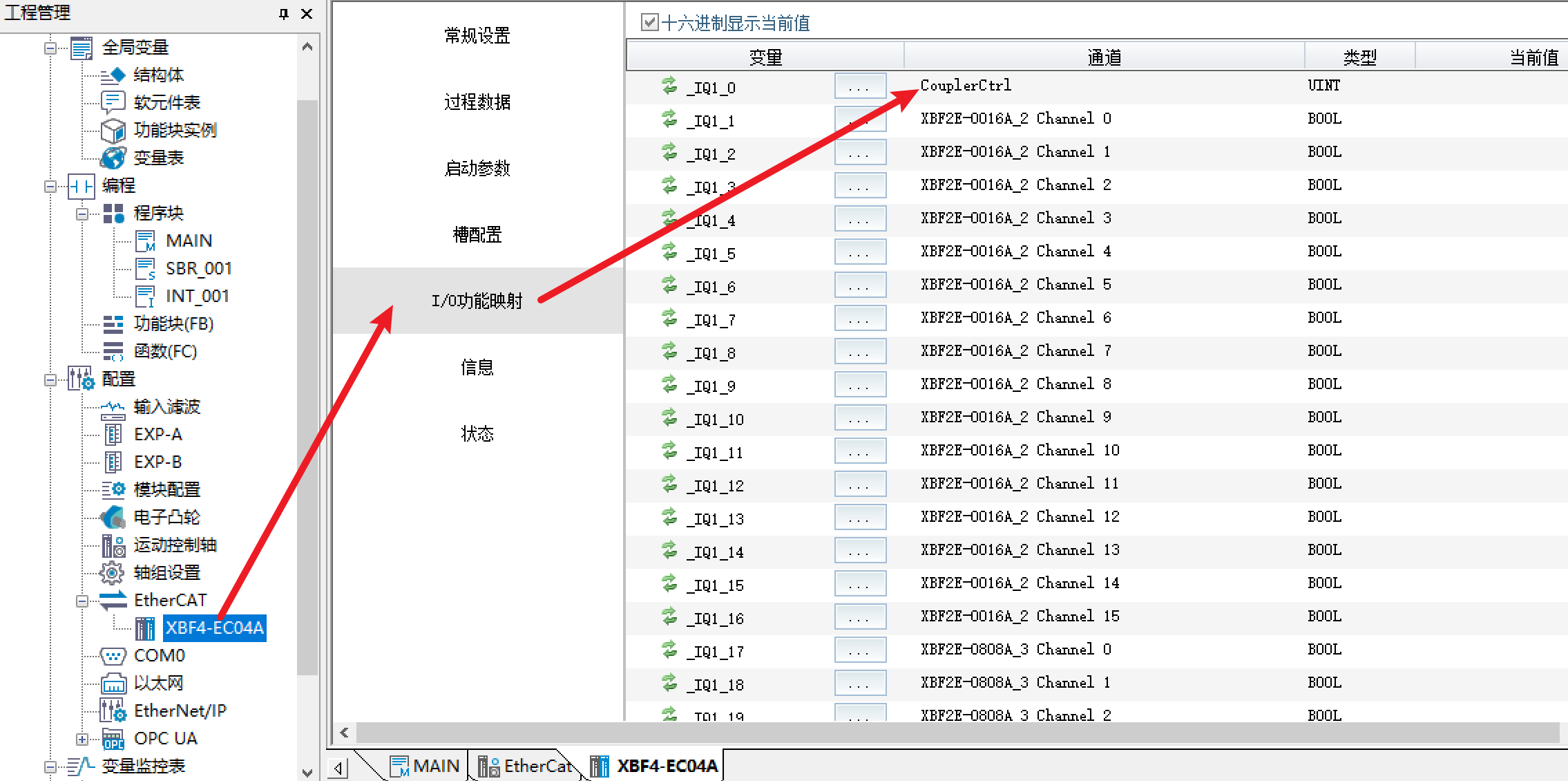
CouplerCtrl is reserved at the beginning of the output address area and has no practical meaning; skip it. After CouplerCtrl, the valid output addresses start from slot number 2 (XBF2E-0016A), arranged in order of increasing slot numbers until the last module.
2. Input Address Mapping Description
CouplerState is reserved at the beginning of the input address area and has no practical meaning; skip it.
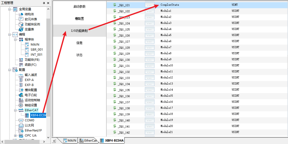
After CouplerState, there are 32 bytes (Module1~Module32) for storing the expansion interface number and hardware DIP switch station number of each module. This is diagnostic information, not actual process input data.
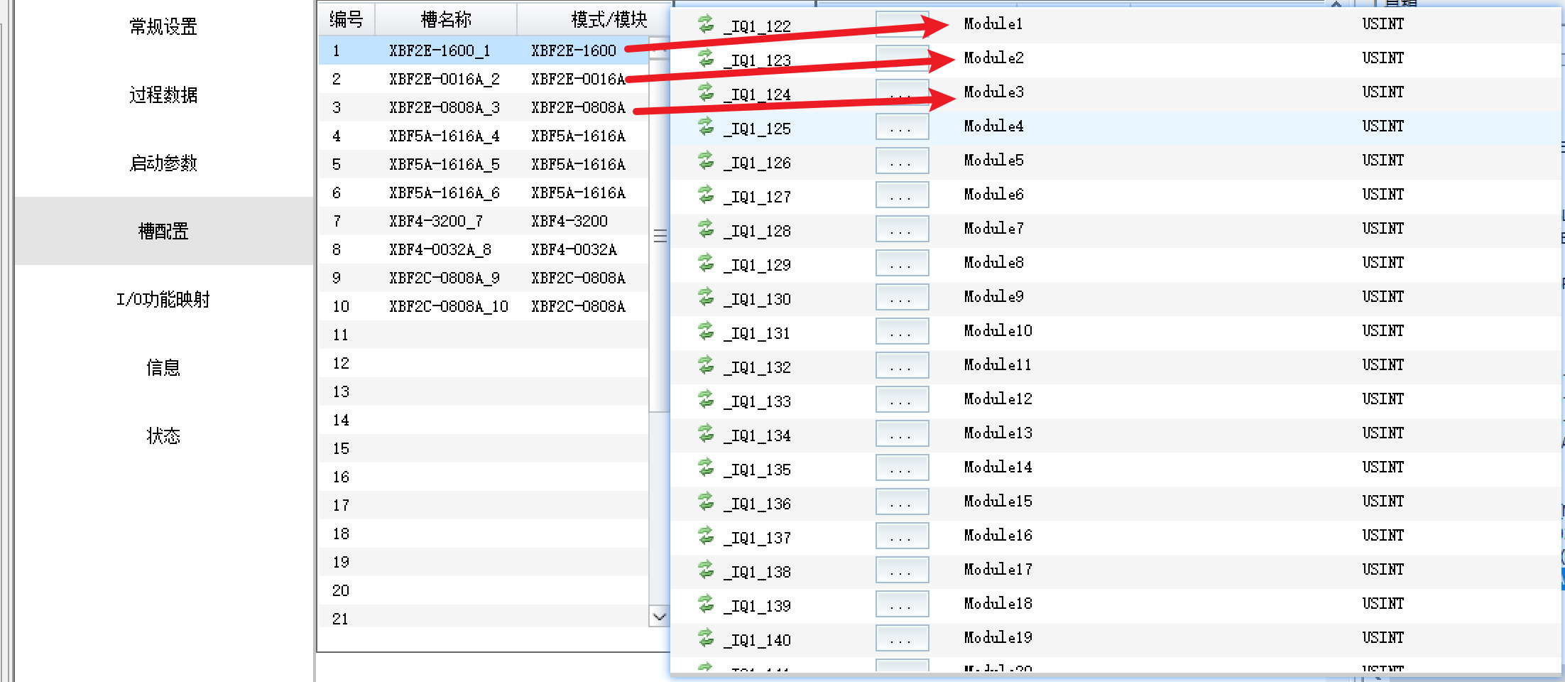
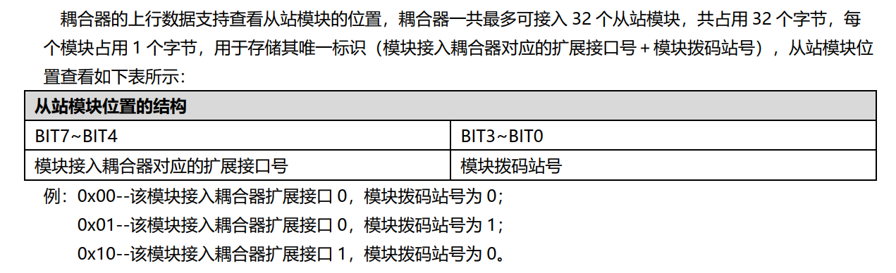
The actual valid input addresses start after Module32, also arranged in order of increasing slot numbers (in this example: slots 1, 3, 4, 5, 6, 7, 9, 10).
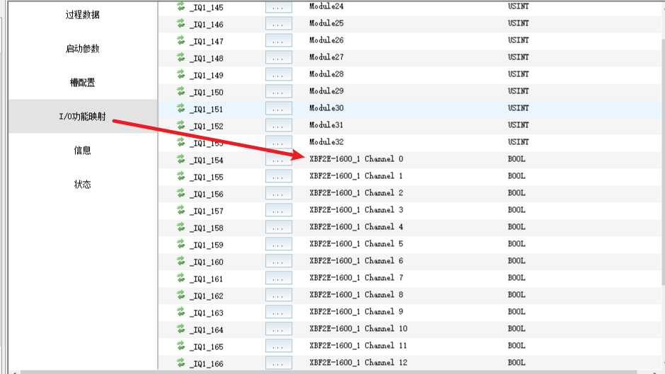
Note: Module1~Module32 are diagnostic information areas and do not contain actual I/O data. Actual input data starts after Module32. When configuring variable binding, be sure to start from the correct position to avoid address offset errors.
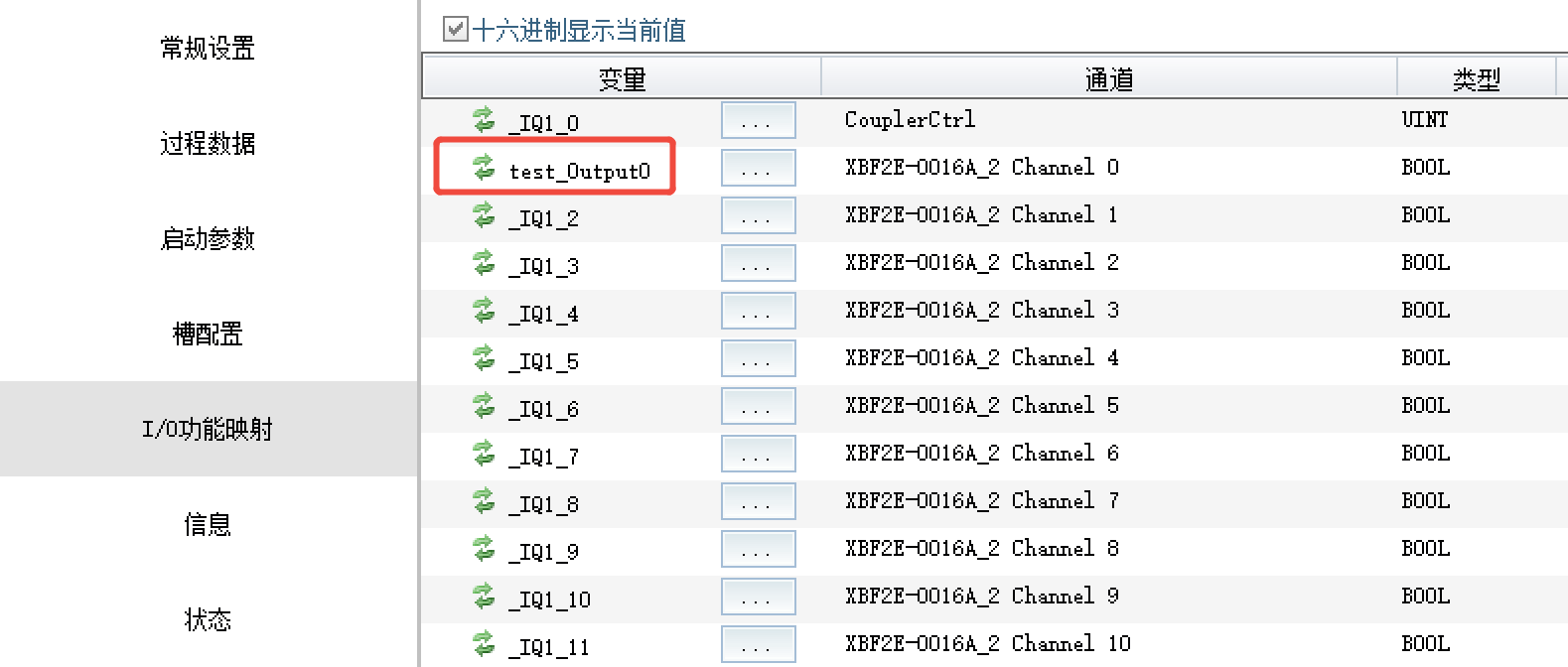
V. Variable Binding and Global Variable Configuration
After address allocation, associate I/O addresses with program variables as follows:
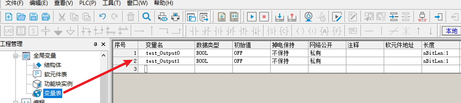
Create the desired custom variables in the [Variable Table].
Enter [I/O Function Mapping], select the I/O address to bind, and select the corresponding variable in the table to complete the association.
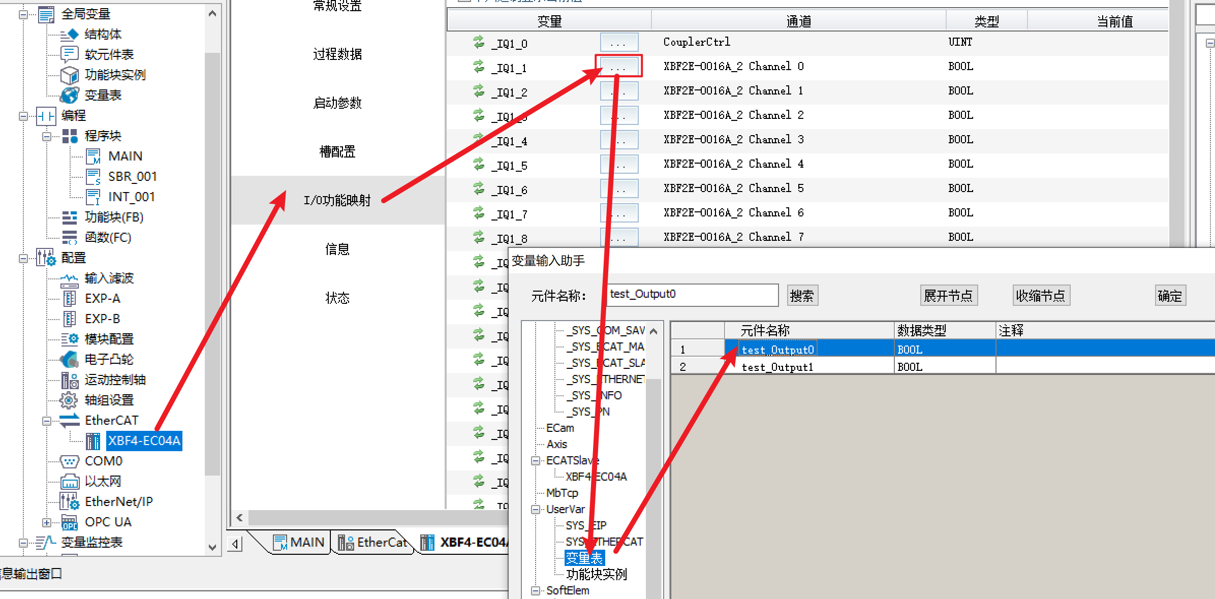
After successful association, the bound channel information can be viewed in the mapping list (e.g., Channel0 of XBF2E-0016A_2 is successfully bound to the specified variable).
Through auto-scan and slot order rules, configuration efficiency and address management accuracy can be greatly improved.