Knowledge

How to complete the configuration of C2P series EtherCAT protocol valve island in KV-Studio
Article Overview
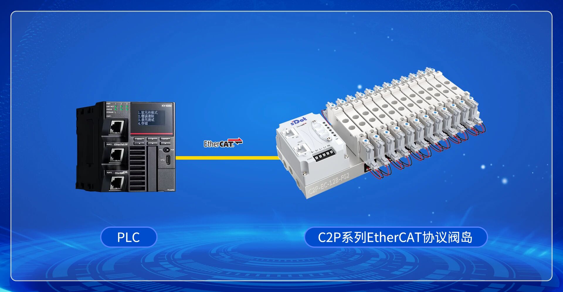
1. Demo Product
C2P Series EtherCAT Valve Island
2. Platform
Keyence KV-X310 PLC + KV-Studio Ver12G
3. Communication Protocol
EtherCAT
4. Configuration Process
New project → Set password → Communication connection → Configuration → Module configuration → PDO mapping → Download to PLC
5. Key Notes
When adding configuration manually, module slot configuration must be completed, otherwise communication will fail. The reference clock function in advanced settings must not be enabled.
How to complete the configuration of the Solidot C2P series EtherCAT protocol valve island in Keyence KV-Studio and achieve I/O control?
This article uses the KV-X310 PLC with KV-Studio Ver12G as an example, introducing the complete operation process: new project, communication connection, ESI file registration, automatic configuration, module slot settings, PDO mapping, and downloading the configuration to the PLC.
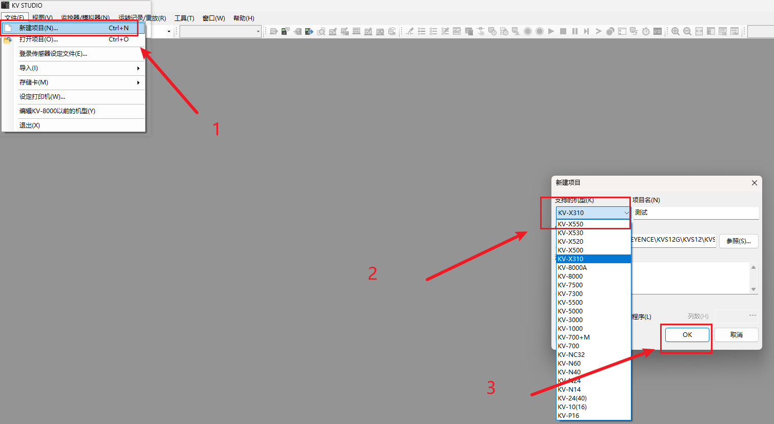
I. New Project
Open KV-Studio, create a new project, and select the corresponding PLC model according to the actual hardware.
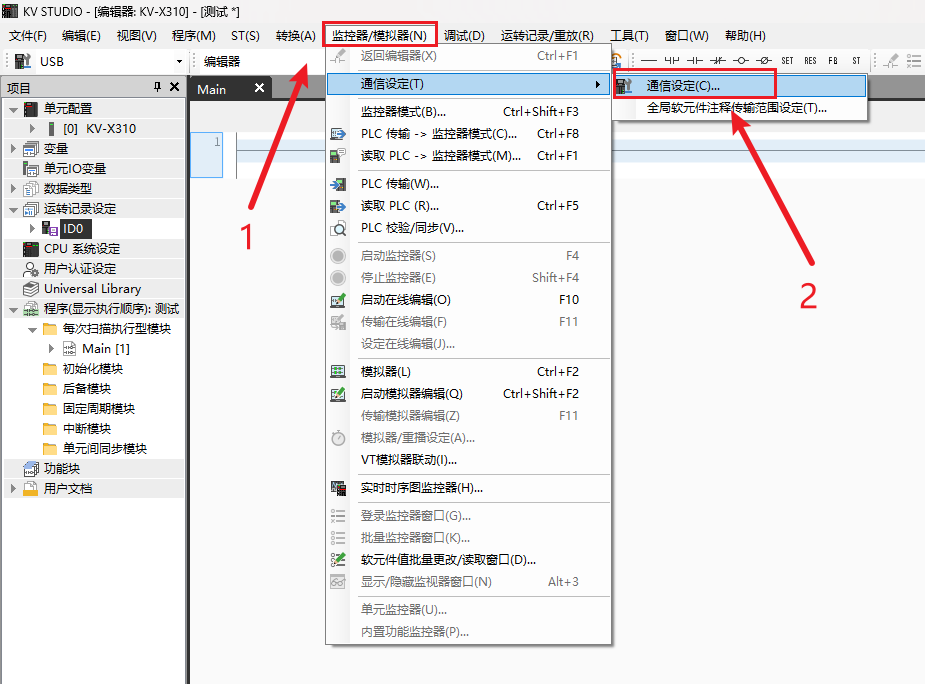
After creation, the software will pop up an administrator password setting window. Enter a password and click "OK" to proceed.

II. Communication Connection
Click "Monitor/Simulator", then click "Communication Settings" in the pop-up window to enter the communication settings interface.
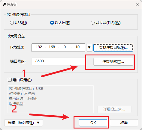
Select the communication port according to the actual network topology. This example uses Ethernet. Select "Ethernet", click "Find Connection Target", select the corresponding network card in the pop-up window, and click "Search". After finding the PLC, select it, click "Select", then click "Connection Test" to confirm normal connection, and finally click "OK" to complete the settings.


III. Configuration
1. Enter EtherCAT Configuration Interface
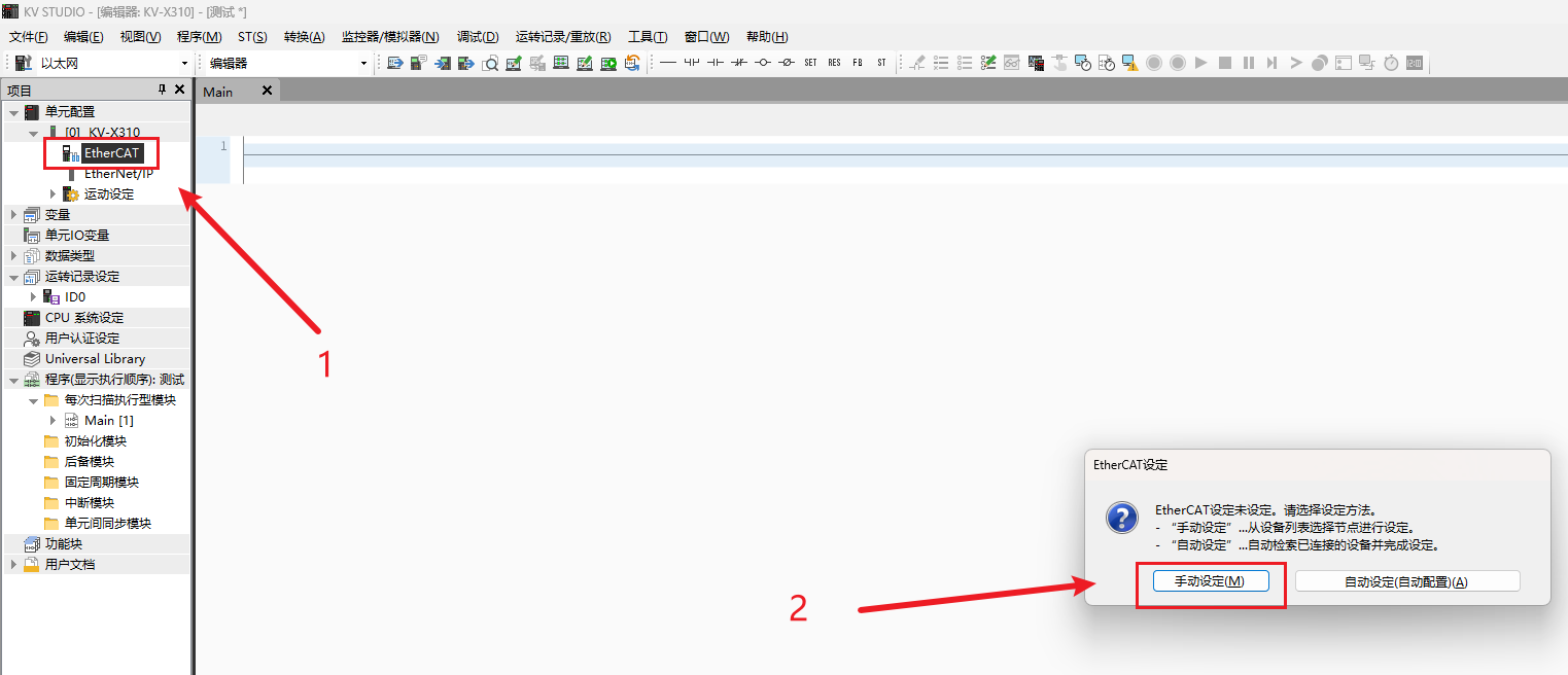
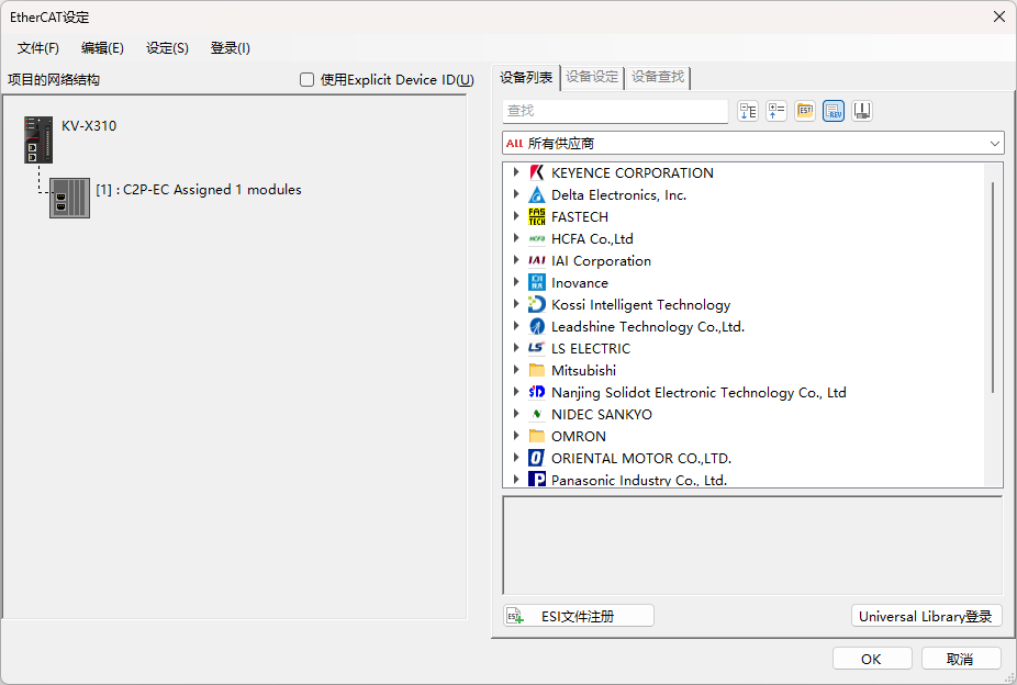
Double-click "EtherCAT", then click "Manual Setting" to enter the configuration interface.
2. Register ESI File
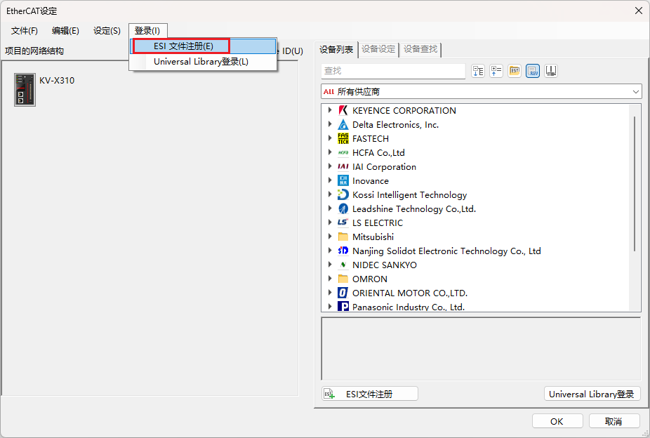
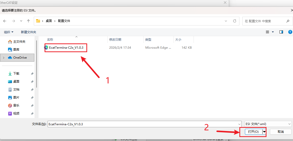
Double-click "Login", click "ESI File Registration", find the configuration file corresponding to the C2P series EtherCAT valve island, and click "Open" to complete registration.
3. Automatic Configuration
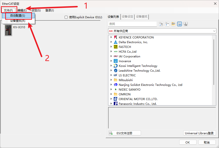
Click "File" → "Automatic Configuration", wait for completion, and click "OK". The configuration is then complete.

IV. Module Configuration
Double-click the C2P series EtherCAT valve island in the configuration to open the "Detailed Setting" window. In the module configuration interface, select the corresponding slot configuration according to the actual model. Auto-scan can automatically identify connected modules. If adding manually, you must manually complete the slot configuration here; otherwise, communication cannot be established.
Set "Extension Setting" to "Use" to configure the module's SDO parameters. If the current module has no SDO parameter requirements or you want to keep defaults, this item can be left unchanged.

Note: When adding configuration manually, module slot configuration is mandatory. If skipped, communication will not be established. Be sure to complete the configuration according to the actual model.
V. PDO Mapping
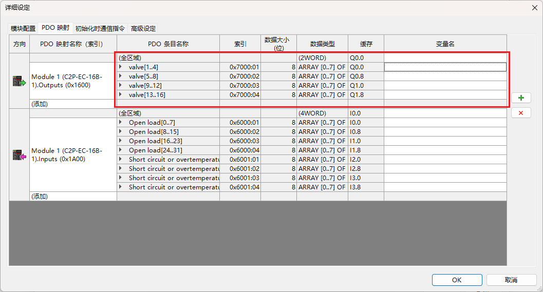
After module configuration and adding the valve island, PDO mapping is completed automatically. The "Cache" column shows the soft element cache address corresponding to each channel. When reading/writing I/O signals in the program, you need to use the UREAD (read cache) and UWRIT (write cache) instructions.

VI. Initialization Communication Instructions and Advanced Settings
1. Initialization Communication Instructions
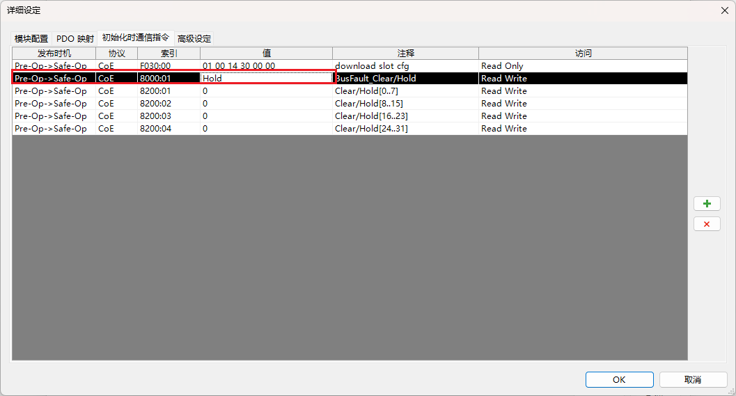
Used to configure initialization instructions for modifying module SDO parameters. Right-click the gray area, click "Add" to view the list of SDO parameters supported by the current module, and add as needed.
2. Advanced Settings
No additional configuration is required in advanced settings.
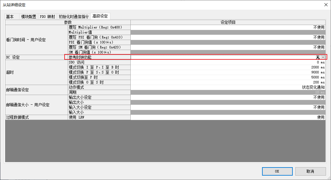
Note: This module only supports Free Run sync mode. The "Reference Clock" function in advanced settings must not be enabled, otherwise communication stability will be affected.
VII. Download Configuration to PLC
After completing all the above configurations, download the configuration and program to the PLC, switch to online mode to confirm normal communication, and then I/O control operations can be performed.