How to use XB6S-MT2002 with Slice XB6S-PL20 and XB6S-PL20D modules?
Article Overview
1. Demo Products
XB6S-PL20 (24V single-ended) / XB6S-PL20D(5V differential)
2. Bus Platform
Modbus TCP (with coupler XB6S-MT2002)
3. Supported Signals
ABZ quadrature signal / direction-pulse signal / dual-pulse signal
4. Operations Involved
Wiring method selection / address lookup in configuration information / Modbus Poll master read/write verification / count enable test
5. Difference between the two
PL20 supports 24V single-ended signals; PL20D supports 5V differential signals. All other usage methods and data structures are identical.
On the Modbus TCP platform, how to use the Solidot Modbus TCP protocol coupler XB6S-MT2002 with the slice counting modules XB6S-PL20/PL20D?
Both XB6S-PL20 and XB6S-PL20D are 2-channel counting modules that support three signal types: ABZ quadrature, direction-pulse, and dual-pulse. The only difference between the two modules is their wiring specifications –PL20 supports 24V single-ended signal input, while PL20D supports 5V differential signal input. All other usage methods and Modbus data structures are completely identical. This article uses XB6S-PL20 as an example to introduce the complete operation process: wiring method selection, address lookup, Modbus Poll master read/write verification, and count enable testing.
PART.01 Comparison of the two modules
When selecting a model, choose the corresponding module according to the on-site signal specifications.
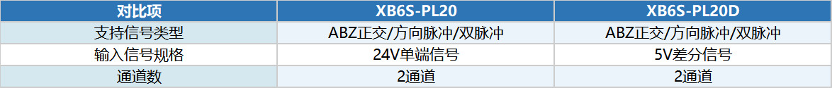
Note: The operation steps in this article are demonstrated using XB6S-PL20 . The usage method and data structure of XB6S-PL20D are exactly the same as those of PL20 , only the wiring is different. When using it, refer to the corresponding wiring diagram.
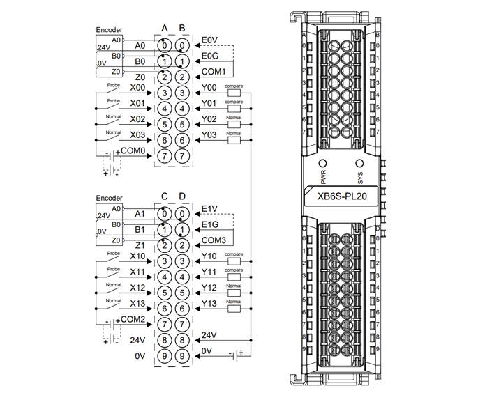
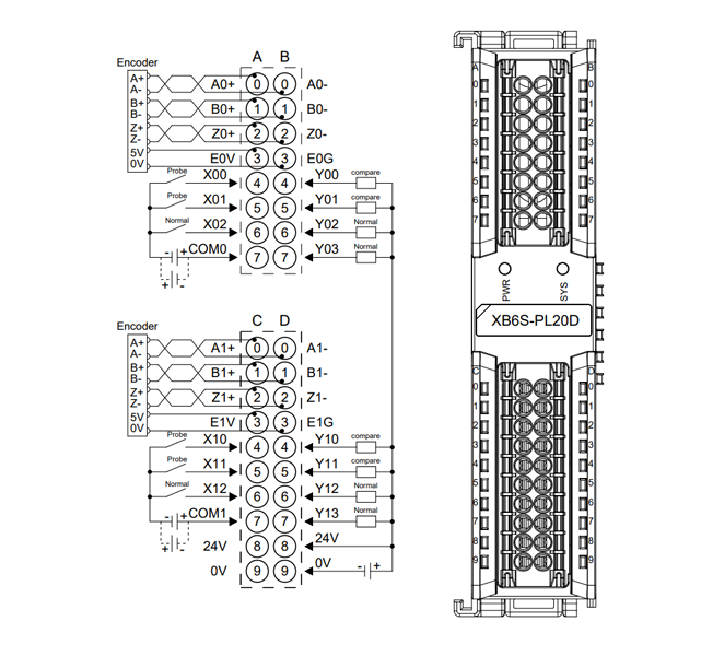
PART.02 Wiring
The wiring diagrams for XB6S-PL20 and XB6S-PL20D are shown below. Please confirm the model to avoid confusion.
PART.03 View module data addresses
Enter 192.168.1.120 in the browser address bar to log into the XB6S-MT2002 web configuration interface. Click "Configuration Information" to view the uplink (read) and downlink (write) data addresses corresponding to XB6S-PL20.
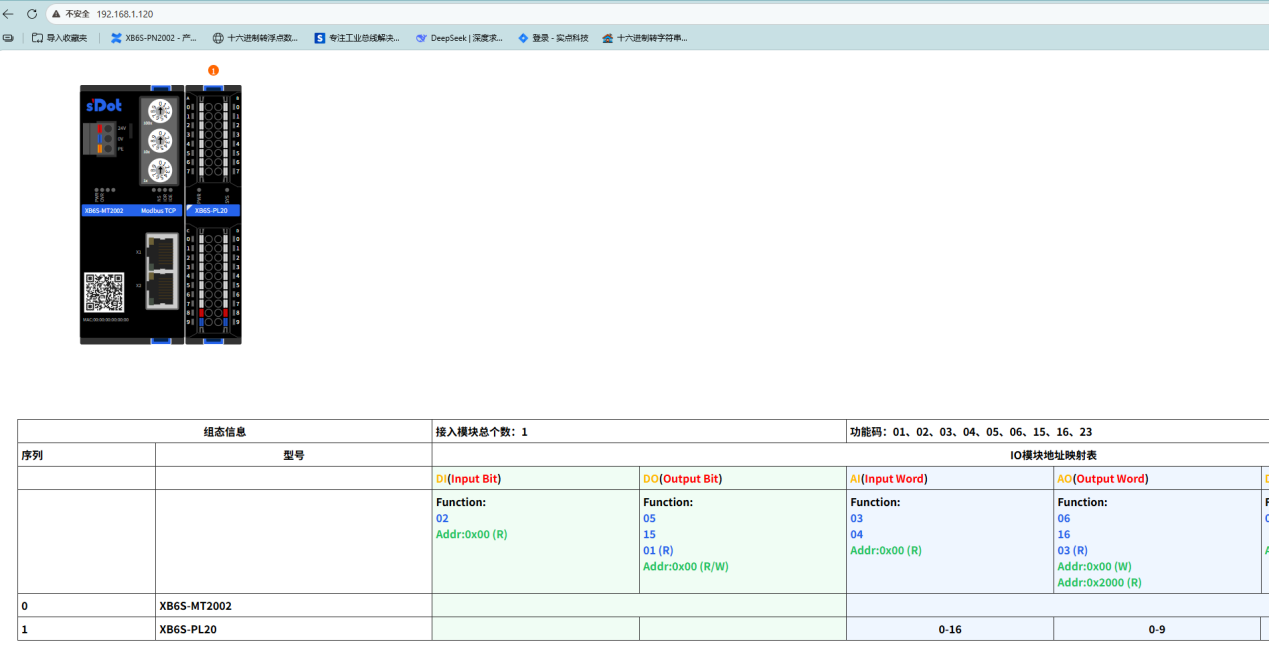
Note: The uplink and downlink data lengths of XB6S-PL20 and XB6S-PL20D are identical, and the address lookup method is the same.
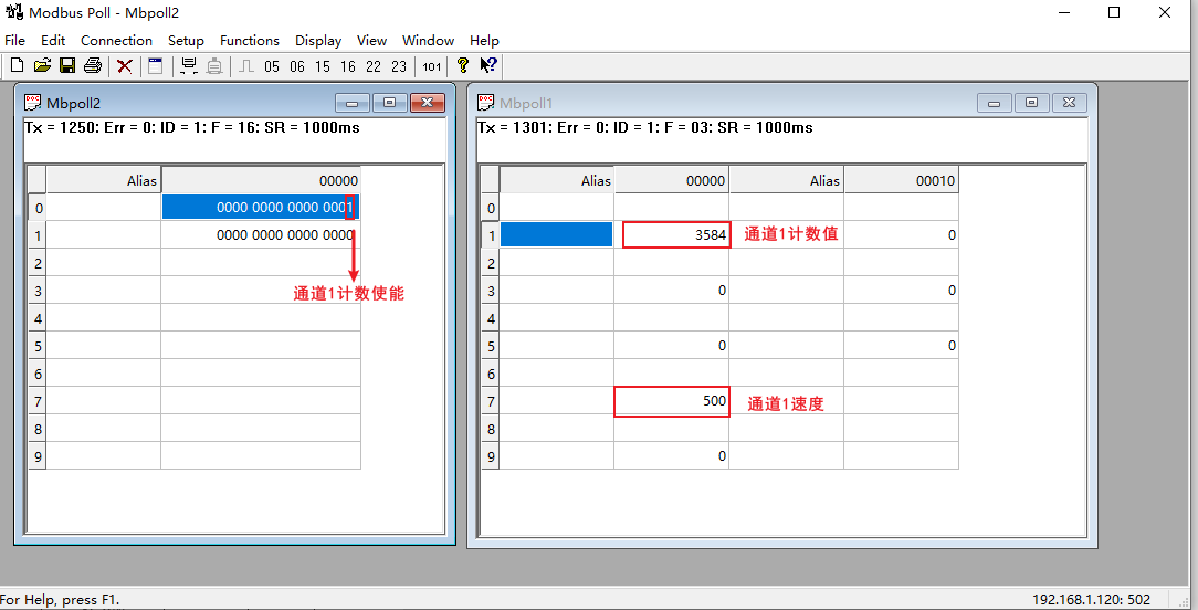
PART.04 Modbus Poll master read/write verification
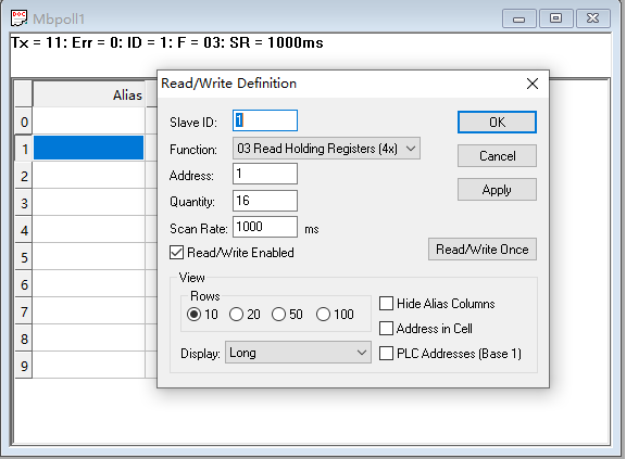
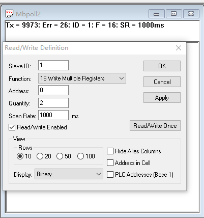
Use Modbus Poll software as the master. According to the addresses found in the configuration information, configure the read and write parameters respectively:
Read settings:
Write settings:
Read settings: Configure read parameters according to the uplink data addresses, corresponding to the count value and status data reported by the module to the master.
Write settings: Configure write parameters according to the downlink data addresses, corresponding to the control commands sent by the master to the module (e.g., count enable).

The data correspondence is based on the uplink/downlink address table in the configuration information page.
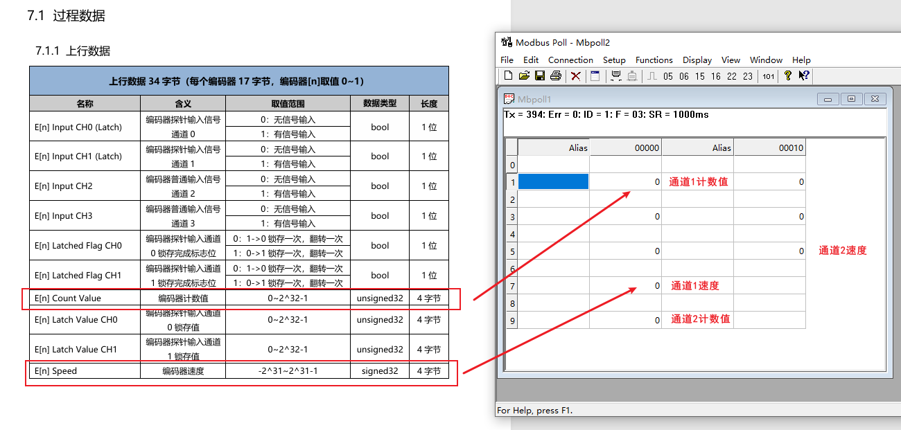
PART.05 Count enable and test
Connect a pulse generator to channel 1 of XB6S-PL20 . Write to the corresponding downlink address via Modbus Poll to enable counting. The module will start counting. Monitor the corresponding uplink address in the read area to observe the count value changes in real time and verify whether the counting function is normal.