How to configure XB6S-PN2002 with XB6S-C01SP as Modbus RTU master in TIA Portal
Article Overview
1. Demo Products
2. Configuration Tool
Siemens TIA Portal
3. Communication Mode
XB6S-C01SP configured as Modbus RTU master, connected to Siemens PLC via XB6S-PN2002
4. Demo Slave
An encoder supporting Modbus RTU protocol (read/write operations with function codes 03/06/10)
5. Operations Involved
Serial port parameter configuration, control word setting, node parameter filling, I/O address read/write, and communication status judgment
How to use the Solidot slice PROFINET protocol coupler XB6S-PN2002 together with the serial communication module XB6S-C01SP in TIA Portal to connect a Siemens PLC to a Modbus RTU slave device and achieve register read/write?
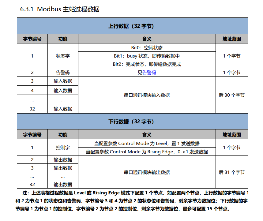
The XB6S-PN2002 handles communication with the PLC on the PROFINET side, while the XB6S-C01SP serves as the Modbus RTU master on the serial side. When used together, all operations including serial port parameter configuration, node command filling, and I/O address read/write can be completed in TIA Portal. This article uses an encoder supporting the Modbus RTU protocol as an example to demonstrate the complete configuration method for function codes 03, 06, and 10.
I. Slave Description in This Demo
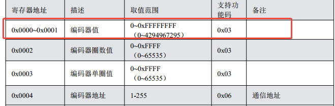
This example uses an encoder that supports the Modbus RTU protocol as the slave. The following three target register operations are found in its manual:
Function code 03: Read 2 registers (read current encoder value)
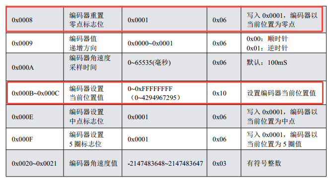
Function code 06: Write a single register (reset zero point)
Function code 10: Write 2 registers (set current position)
II. Configure Serial Communication Parameters in TIA Portal
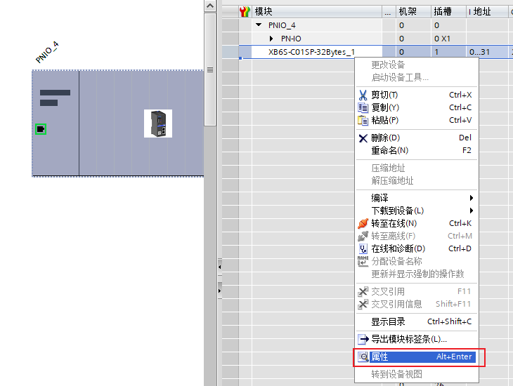
In TIA Portal, select the XB6S-C01SP module, click "Properties" → "Module Parameters", and set the communication mode to "Modbus RTU Master".
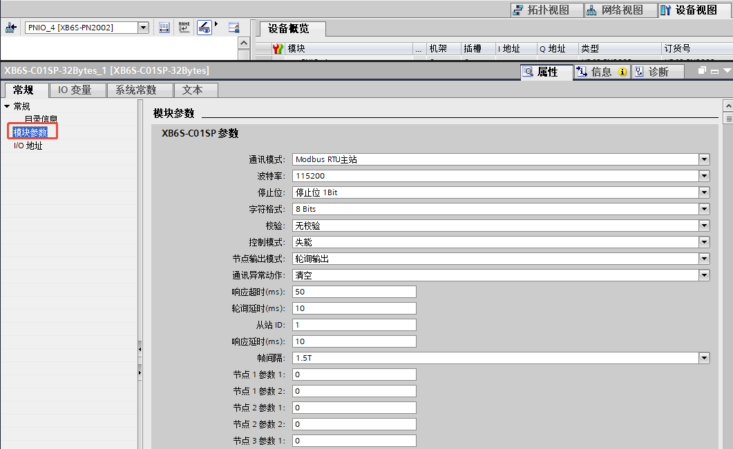
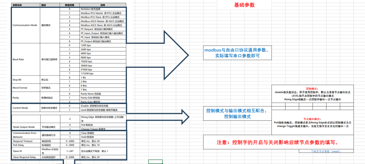
Fill in the baud rate, stop bits, character format, and parity according to the serial parameters of the slave, ensuring the master and slave configurations are identical.
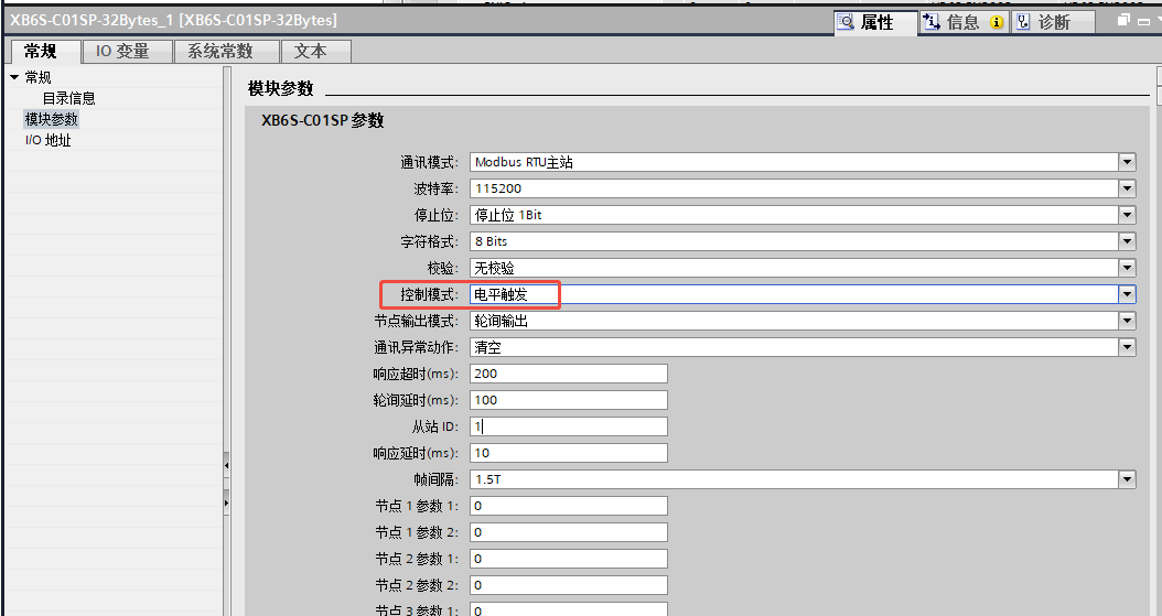
Recommendations for control word related parameters: If a control word is required, it is recommended to select "Level Trigger" as the control mode, set response timeout to 200ms, and polling delay to 100ms for higher communication stability.
Note: The default polling speed is fast; some slow-responding slaves may not respond in time and cause errors. Appropriately increasing the response timeout and polling delay can effectively improve communication stability.
Frame interval parameter: Generally keep the default 1.5T. If the module communicates normally with the serial debugging assistant, and the serial debugging assistant also communicates normally with the slave device, but the module cannot communicate with the slave device, try gradually increasing the frame interval value for testing.
III. Node Parameter Configuration
Under the premise that the communication mode is Modbus RTU master and the control word is enabled, fill in node parameters according to the following rules. This example configures 3 commands, requiring nodes 1 to 4:
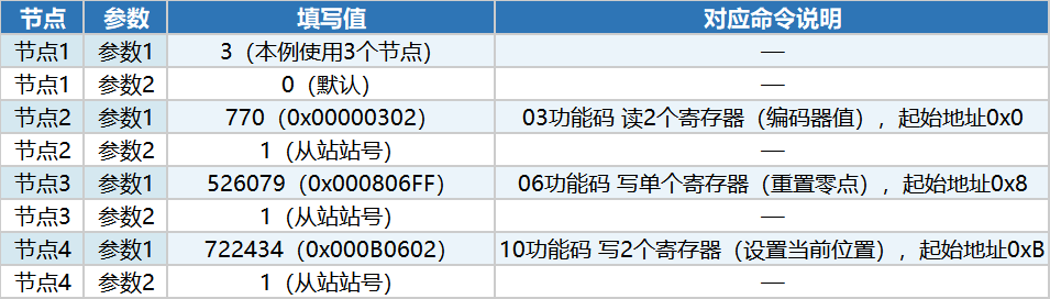
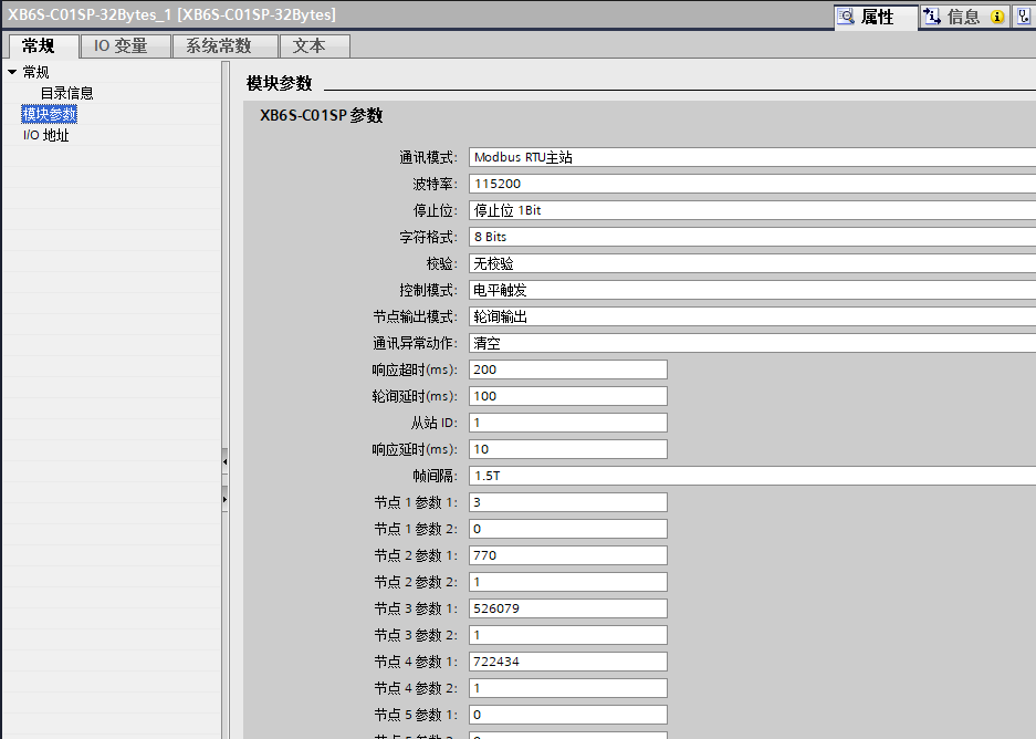
Node 1, Parameter 1: the actual number of nodes used in this example (3)
From Node 2 onwards, each node corresponds to one Modbus command. Parameter 1 is the decimal value converted from hexadecimal format; Parameter 2 is the slave station number.
IV. I/O Address Read/Write and Communication Status Judgment
After configuration, control instructions are sent via Q addresses, and status is read via I addresses.
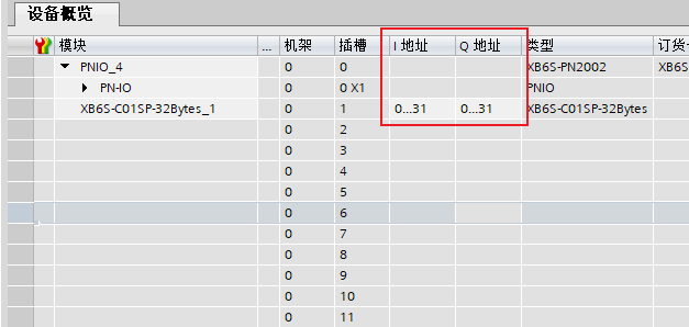
In this example, all addresses start from 0. Definitions are as follows:
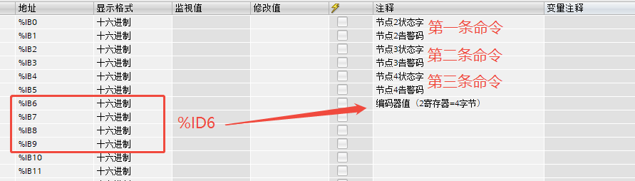
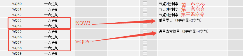
QB0 = 1 enables node 2 to participate in polling. Similarly, to enable node 3 and node 4, set QB1 = 1 and QB2 = 1.
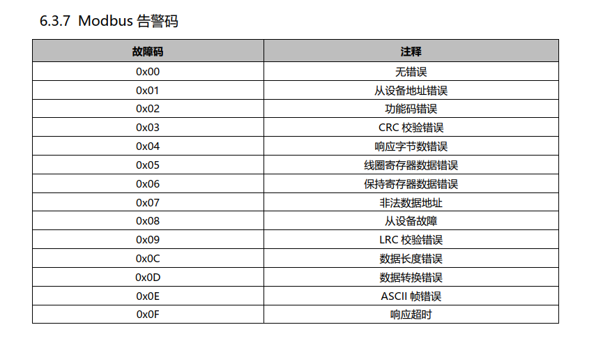
During normal communication, status bits BIT0/BIT1/BIT2 will change. For example, the value of IB0 will generally switch between 2 and 5, and the alarm code remains 0. If communication is abnormal, check the alarm code.