How to complete the configuration of IOL7A-A8C-M12 under EtherCAT protocol in Omron Sysmac Studio
Article Overview
1. Applicable Products
2. Communication Protocol
EtherCAT (via IO-Link MasterIOL7A-EC01B-8A)
3. Configuration Tool
Omron Sysmac Studio
4. Operations Involved
XML file installation, node writing, module configuration, IO-Link status check, global variable binding, mode and range switching
5. Key Notes
Unused ports must be configured as DI; the program must be re-downloaded after each parameter change for the changes to take effect
The IOL7A-A8C-M12 is a Solidot analog input/output voltage/current compatible IO-Link Hub. How to complete its hardware configuration in Omron Sysmac Studio and achieve analog data reading, input/output mode switching, and range modification?
This article introduces the complete operation process in sequence: XML file installation, node writing, module parameter configuration, IO-Link status check, global variable binding, and mode/range switching.
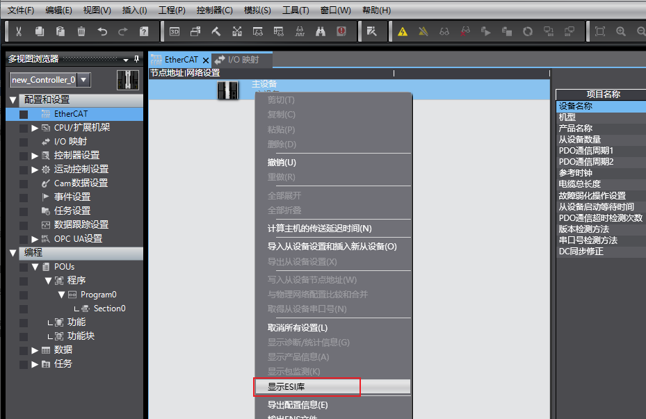
I. Install XML File
Open Sysmac Studio. In the EtherCAT configuration interface, right-click "Master Device" and select "Show ESI Library".
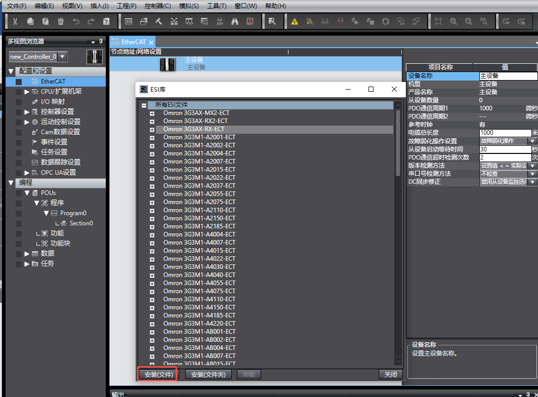
In the ESI Library pop-up window, click "Install (File)", select the corresponding XML file. After installation, close the pop-up window.
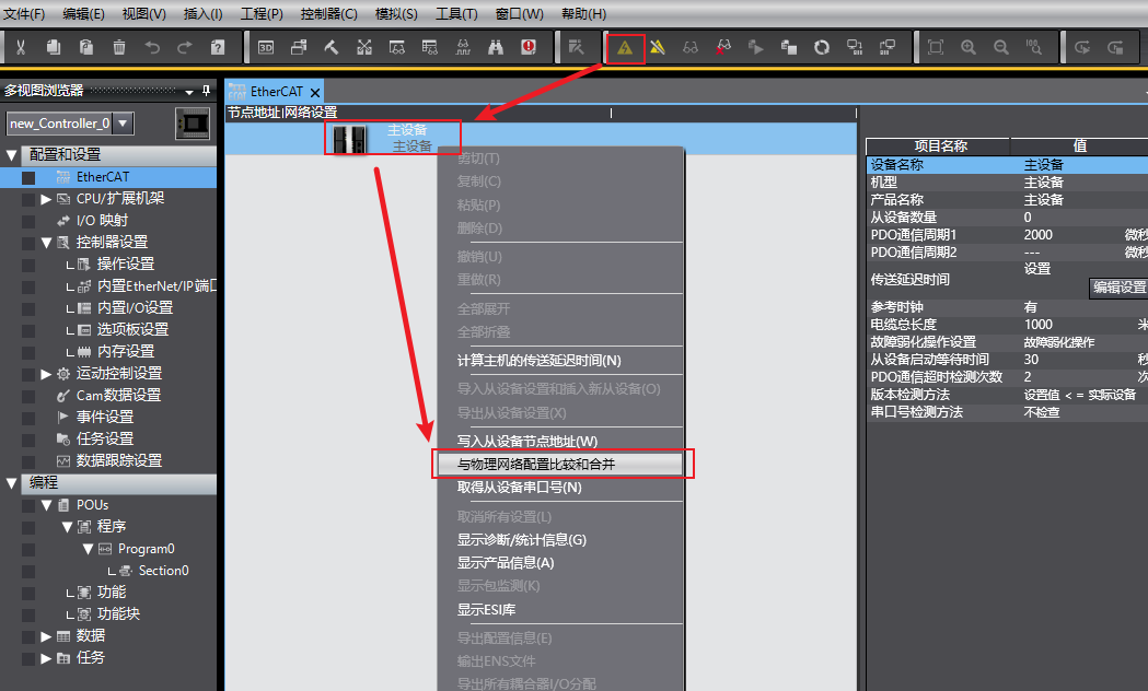
II. Online Scan and Write Node Address
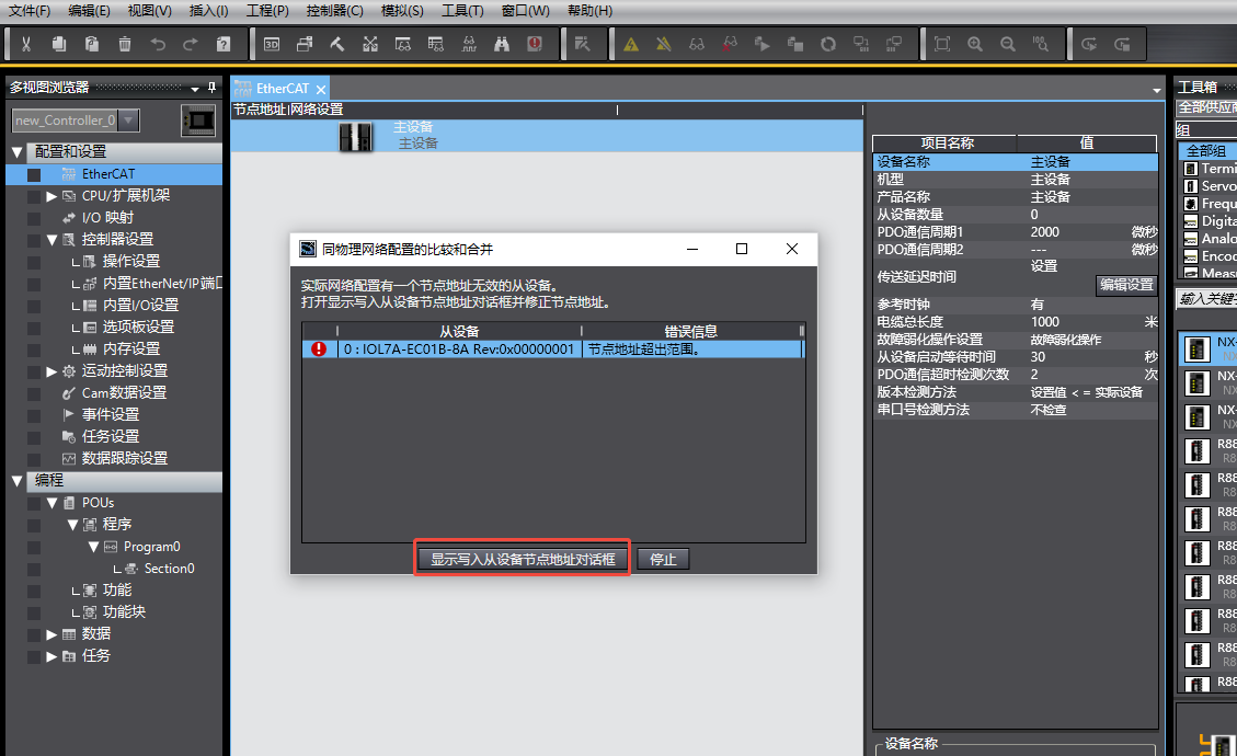
After going online with the PLC, right-click "Master Device" and execute "Compare and Merge with Physical Network Configuration".
If prompted "Node address out of range", open "Show Write Slave Node Address Dialog", correct the node address of IOL7A-EC01B-8A , and click "Write". After writing, power cycle the device for the node address setting to take effect.

After restart, execute "Compare and Merge with Physical Network Configuration" again. In the match interface, select "Apply Physical Network Configuration" to complete device addition.
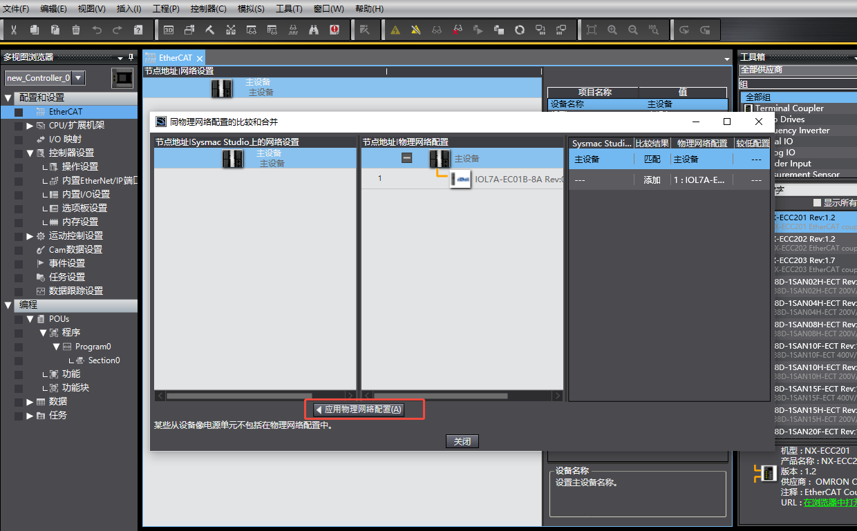
Note: The device must be power cycled after node address writing, otherwise the setting will not take effect and subsequent scans will still report node out-of-range errors.
III. Edit Module Configuration
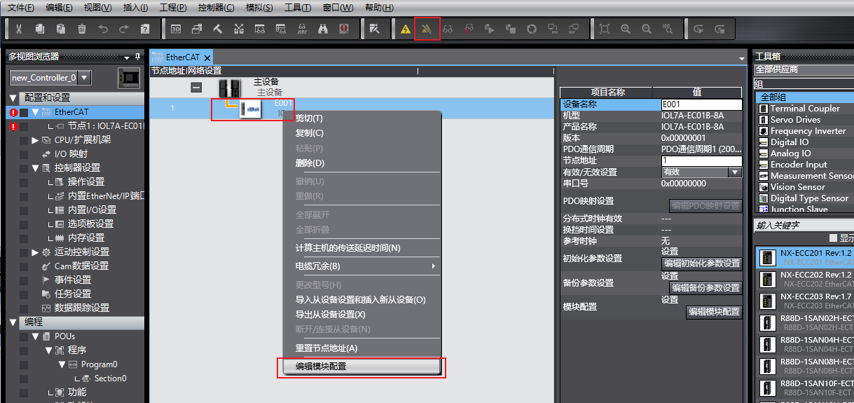
Switch the PLC to offline mode. Right-click the newly added master module IOL7A-EC01B-8A and click "Edit Module Configuration".
Example configuration: Configure 2 IOL7A-A8C-M12 on master ports X00 and X01; ports X02–X07 are unused. However, actually only one IOL7A-A8C-M12 is connected to X00; X01 is not connected.
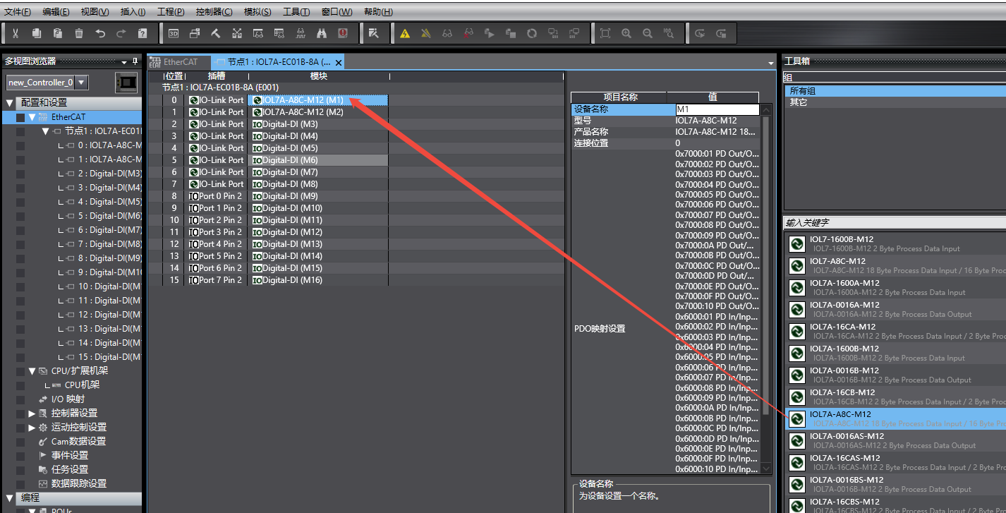
Port configuration rules:
All ports must be configured. Unused ports must be set to DI. If there is an empty slot, the program cannot be downloaded.
When using Solidot IOL7A series slaves, delete the default DI configuration of the port and insert the corresponding slave model.
If auxiliary power supply via PIN2 is required, change the PIN2 of the corresponding PORT to DO and assign a value (In this example, IOL7A-A8C-M12 does not require auxiliary power).
After configuration, switch the PLC back to online mode and download the program to the controller.
IV. IO-Link Status Check
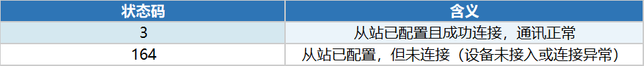
After program download, view the IO-Link status in the "I/O Mapping" interface (Subindex 001–008). Common status code meanings are shown in the table.
V. Global Variable Binding and Data Reading
Process data of analog slaves is output in bytes by default. In practice, two bytes need to be combined into one word. This example uses a union:
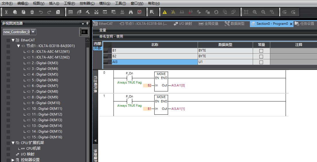
Create a union: In Data Types → Unions, create a new union named U1. Members include a 2-byte array (AI1) and a Word type variable (AI2). The two members are automatically equivalent and can be converted to each other for reading.

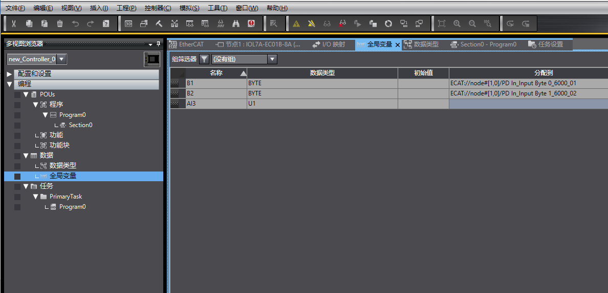
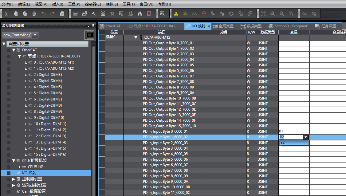
Create global variables and bind to I/O mapping: Create global variables and bind them to the corresponding module addresses in I/O mapping.
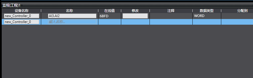
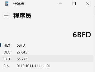
Assign values and monitor in the program: In the program, associate B1 and B2 with the union, and monitor the Word variable in the union to obtain the analog value.
Verification example: The first channel has a default range of 0–10V (corresponding value 0–27648). With an external 10V input, the read value is close to the theoretical value 27648, meeting expectations.
Tip: Using a union is one way to handle byte concatenation, not the only solution. You may use other data processing methods that better suit your project structure.
VI. Analog Input/Output Mode Switching and Range Modification
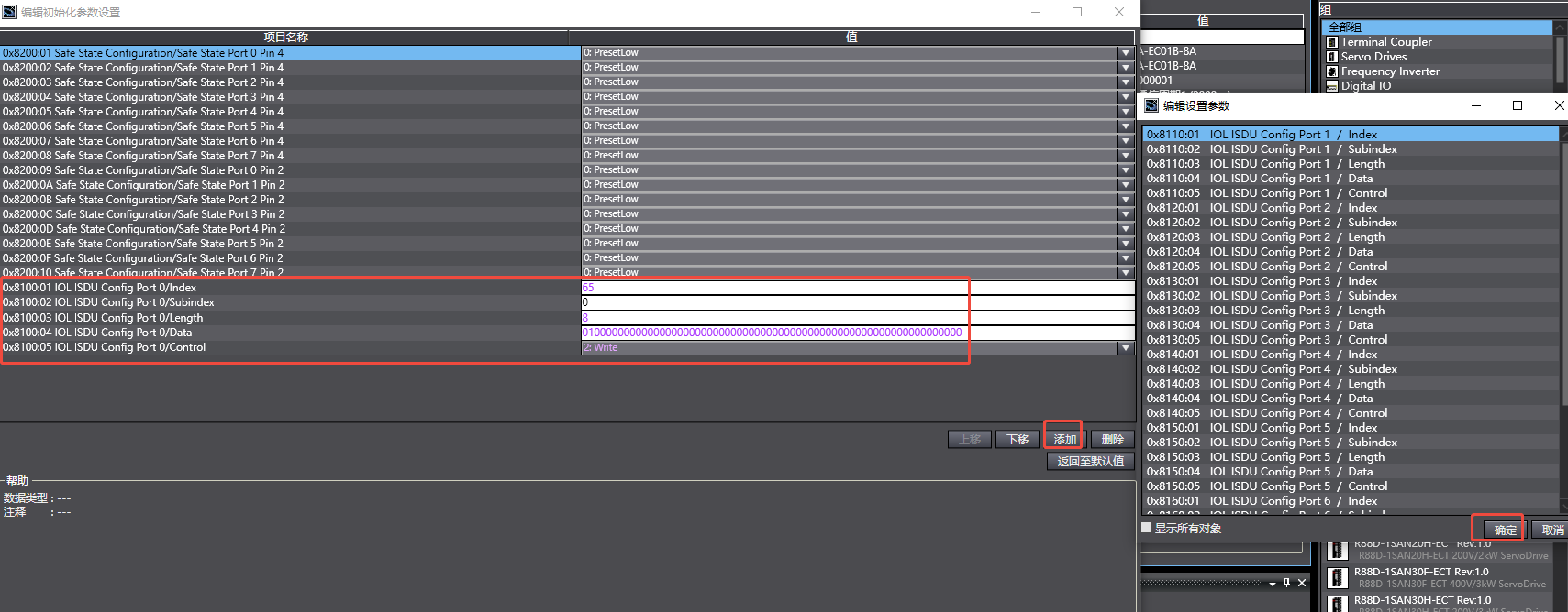
In the module configuration interface, click "Add", select the index, confirm, and write the corresponding parameters to complete mode switching or range modification.


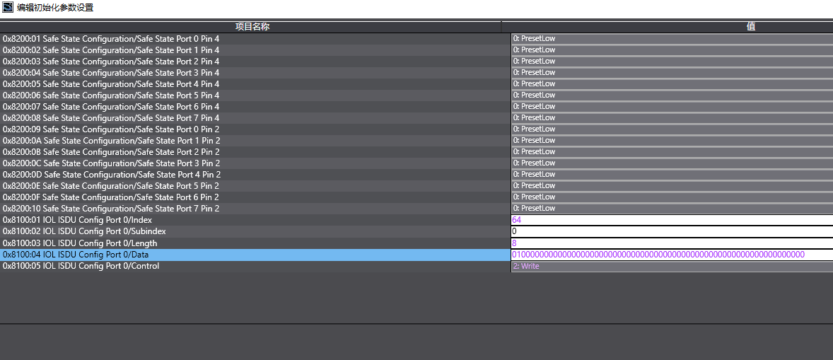
Mode switching example (switch X00 to output mode, keep X01–X07 in input mode):
Index: 64, Subindex: 0, Length: 8, Data: 01,00,00,00,00,00,00,00
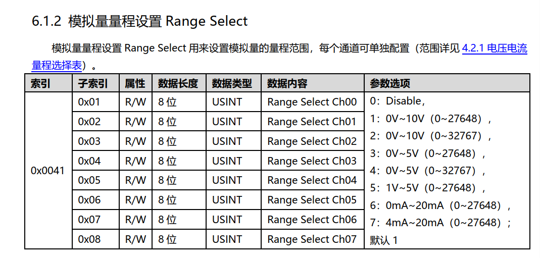
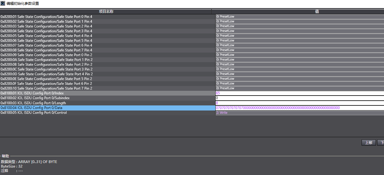
Range modification example (switch all 8 channels X00–X07 to 4–20mA, corresponding value 0–27648):
Index: 65, Subindex: 0, Length: 8, Data: 07,07,07,07,07,07,07,07
Note: After each parameter change, the program must be re-downloaded to the controller for the changes to take effect.