How to configure communication between C3 valve island and discrete coupler in TIA Portal?
Article Overview
1. Demo Products
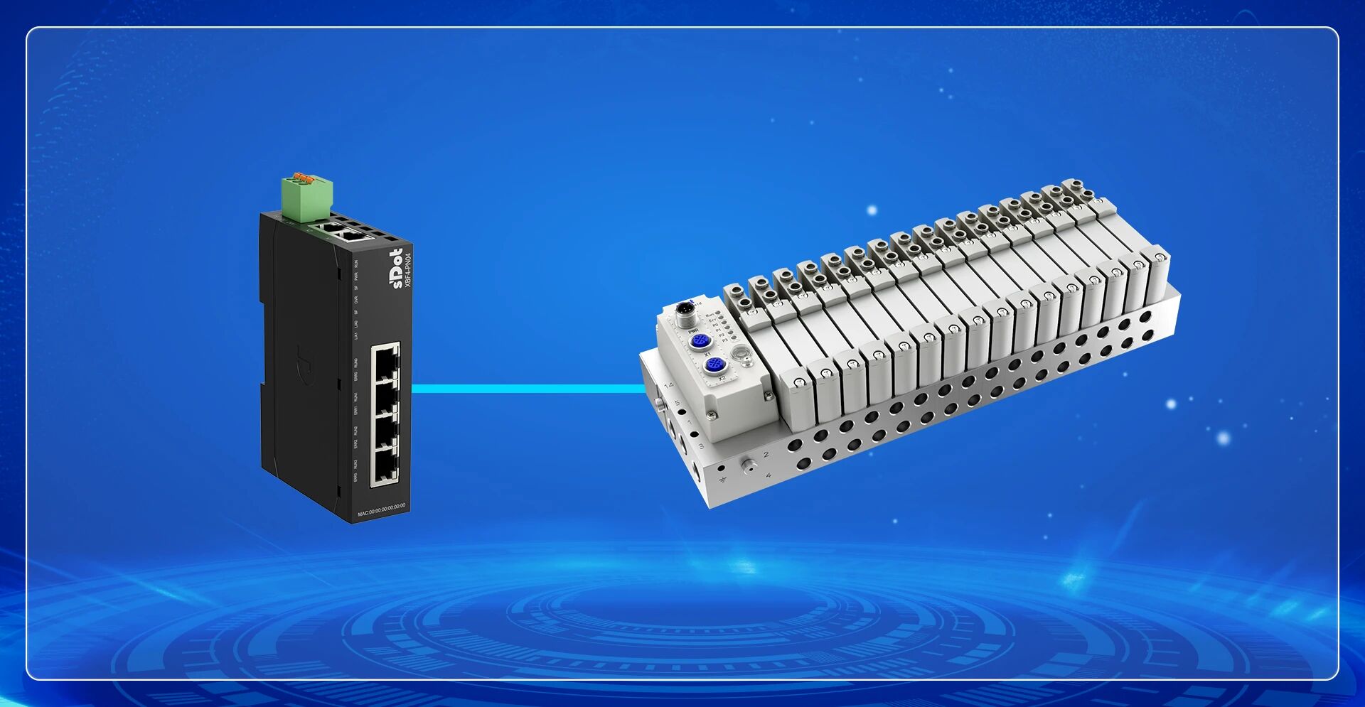
C3 Valve Island + XBF4-PN04
2. Communication Protocol
PROFINET
3. Configuration Tool
Siemens TIA Portal
4. Configuration Process
Install GSD file → Topology configuration → Assign device name → Download hardware configuration → I/O mapping
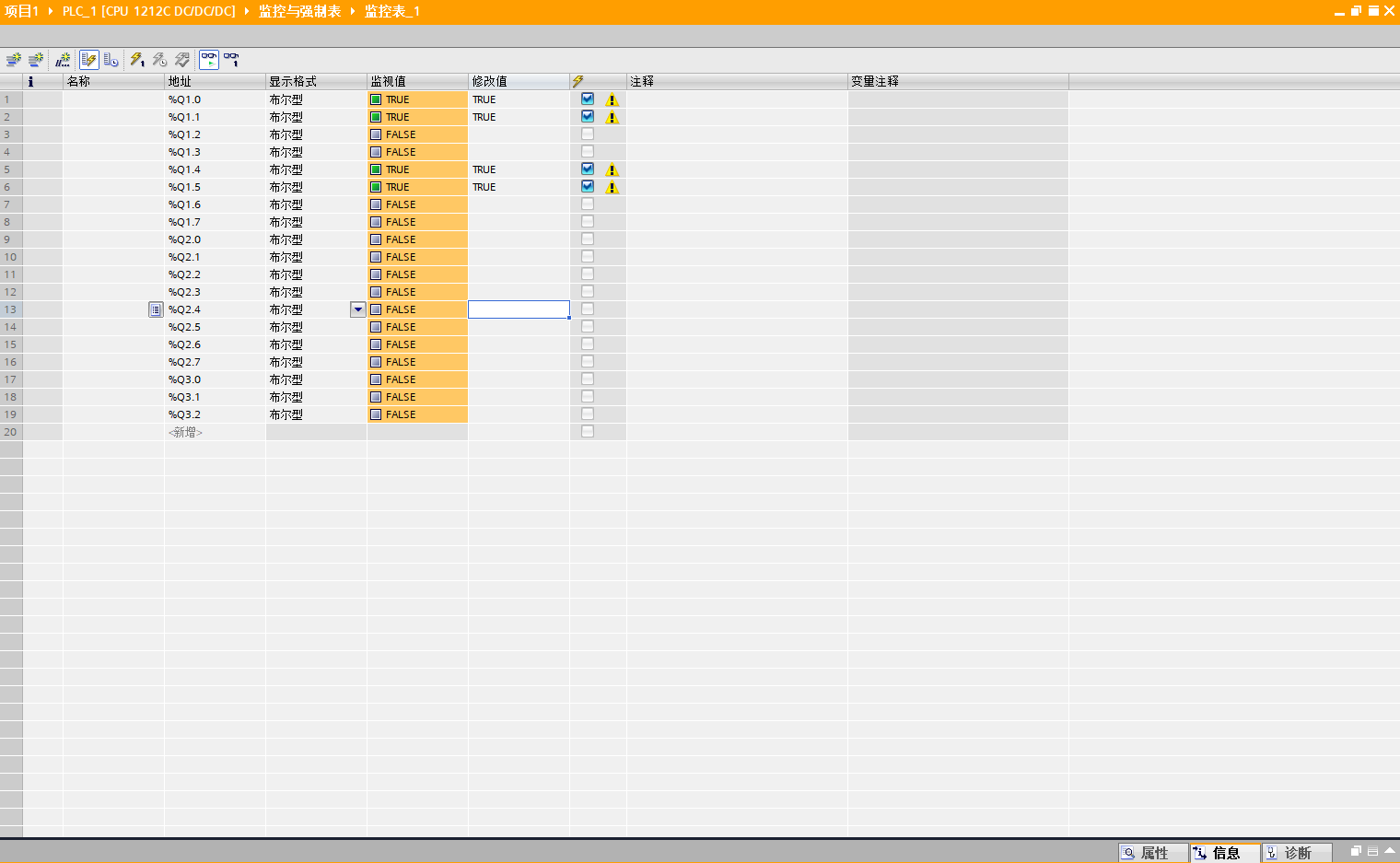
5. Configuration Result
Valve island solenoid valves can be controlled via the TIA Portal monitoring table by writing to the corresponding output addresses
How to configure communication between the Solidot C3 valve island and the discrete coupler in TIA Portal? The configuration requires five steps in sequence: install GSD file, topology configuration, assign device name, download hardware configuration, and I/O mapping. This article uses the C3 valve island (8-bit, station address DIP switch set to 1) and the discrete coupler XBF4-PN04 as examples, following the actual operation sequence.
I. Install GSD File
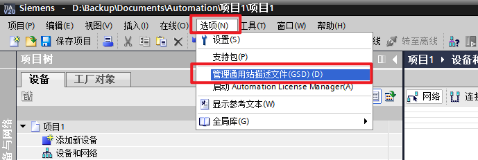
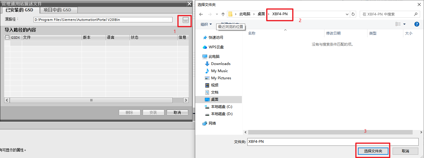
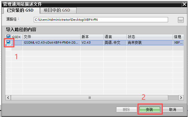
Click "Options" on the TIA Portal menu bar, then double-click "Manage general station description files (GSD)" to enter the GSD file management interface. Click the path selection button "...", select the folder containing the GSD file, check the GSD file to be installed, and click "Install" to complete the import.
II. Topology Configuration
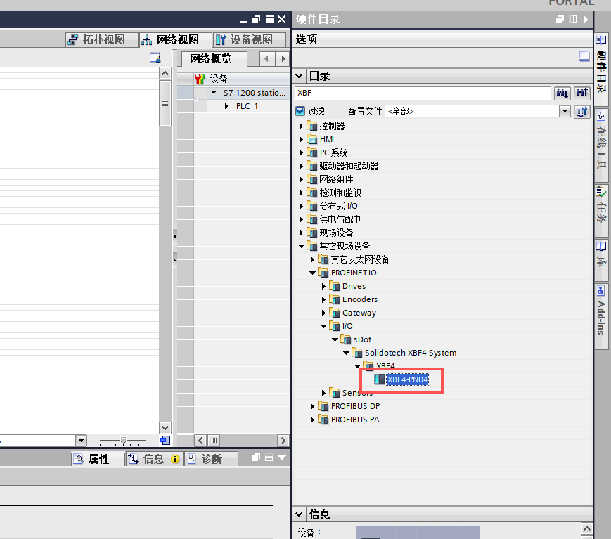
In the TIA Portal hardware catalog, find the device module corresponding to the discrete I/O coupler XBF4-PN04 and double-click to add it to the rack.
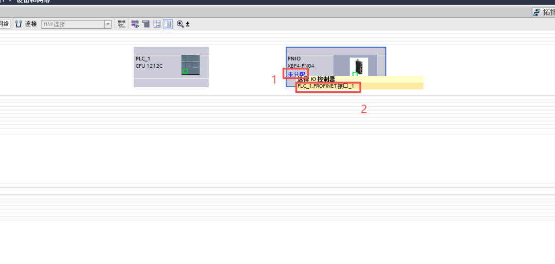
Click "Not assigned" to assign the device module to the corresponding I/O controller.
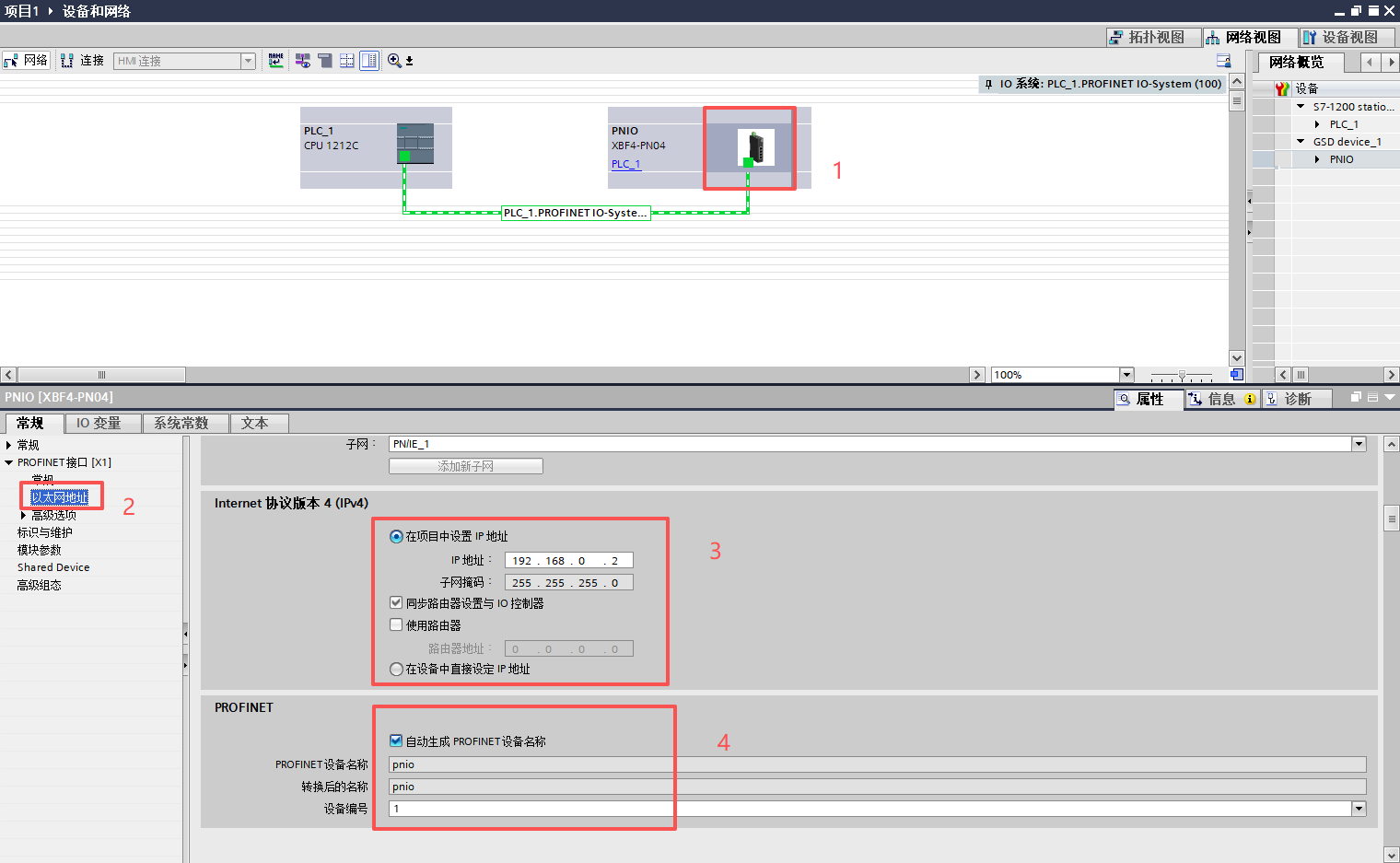
Click on the added module, find the Ethernet address in the properties panel, and modify the IP address and device name according to the actual network plan.
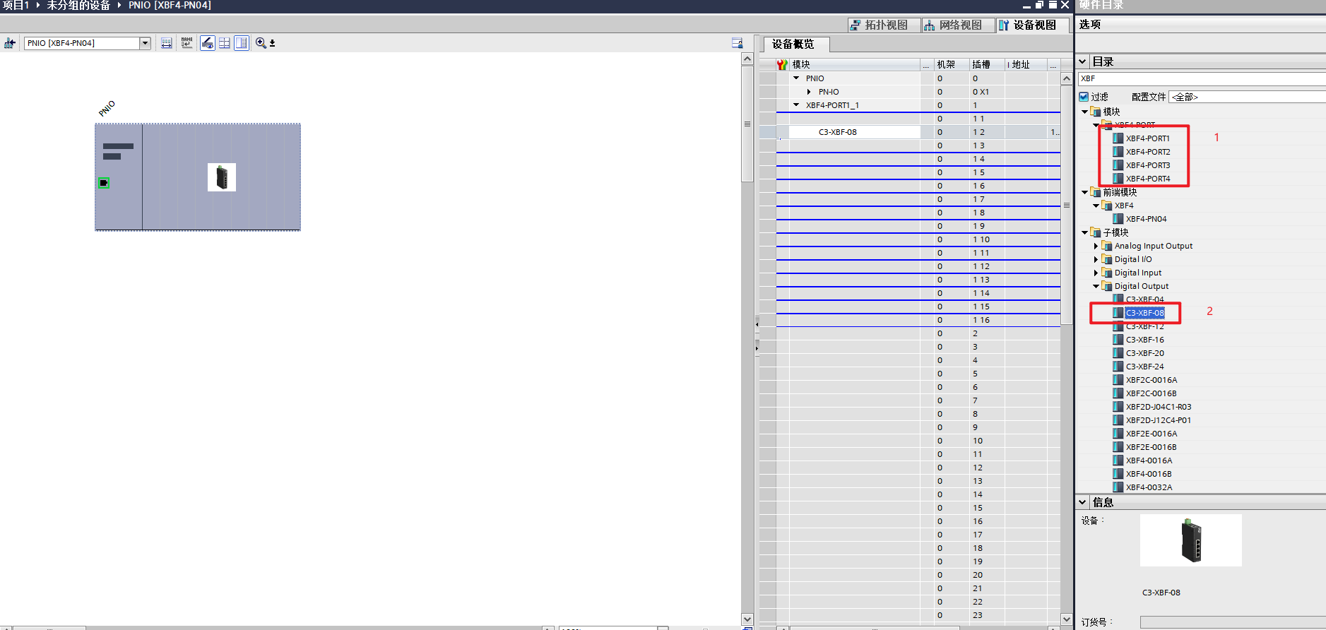
Double-click the module to enter the detailed configuration interface. XBF4-PN04 has 4 network ports. According to the actual port connected by the network cable, first add the corresponding PORT (in this example, the network cable is connected to the first port, so add PORT1 first), then below PORT1, add the valve island submodules in order of the actual model and DIP switch station address (in this example, an 8-bit valve island with station address DIP switch set to 1).
III. Assign Device Name
Switch TIA Portal to online mode, right-click the added coupler module XBF4-PN04, select "Assign device name", and follow the prompts to complete the online writing of the device name.

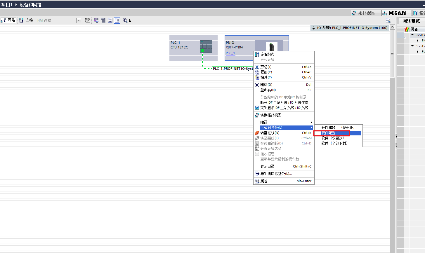
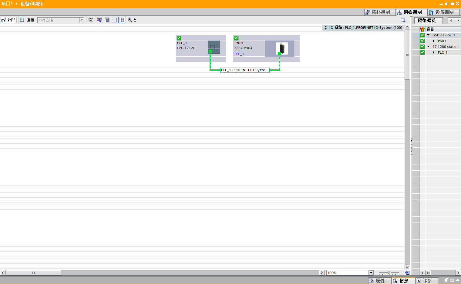
IV. Download Hardware Configuration
Switch TIA Portal to offline mode, right-click the module, select "Download hardware configuration" to complete the download. After the download is complete, switch the PLC back to online mode and confirm that the communication status of the coupler module XBF4-PN04 is normal, indicating that the PROFINET connection has been established.
V. I/O Mapping and Output Test
View and record the I/O address assignment in the module's configuration interface. Enter the corresponding output address in the TIA Portal monitoring table and assign a value (the address in this example is shown in the figure). The solenoid valve on the valve island will act normally, verifying the communication configuration result.
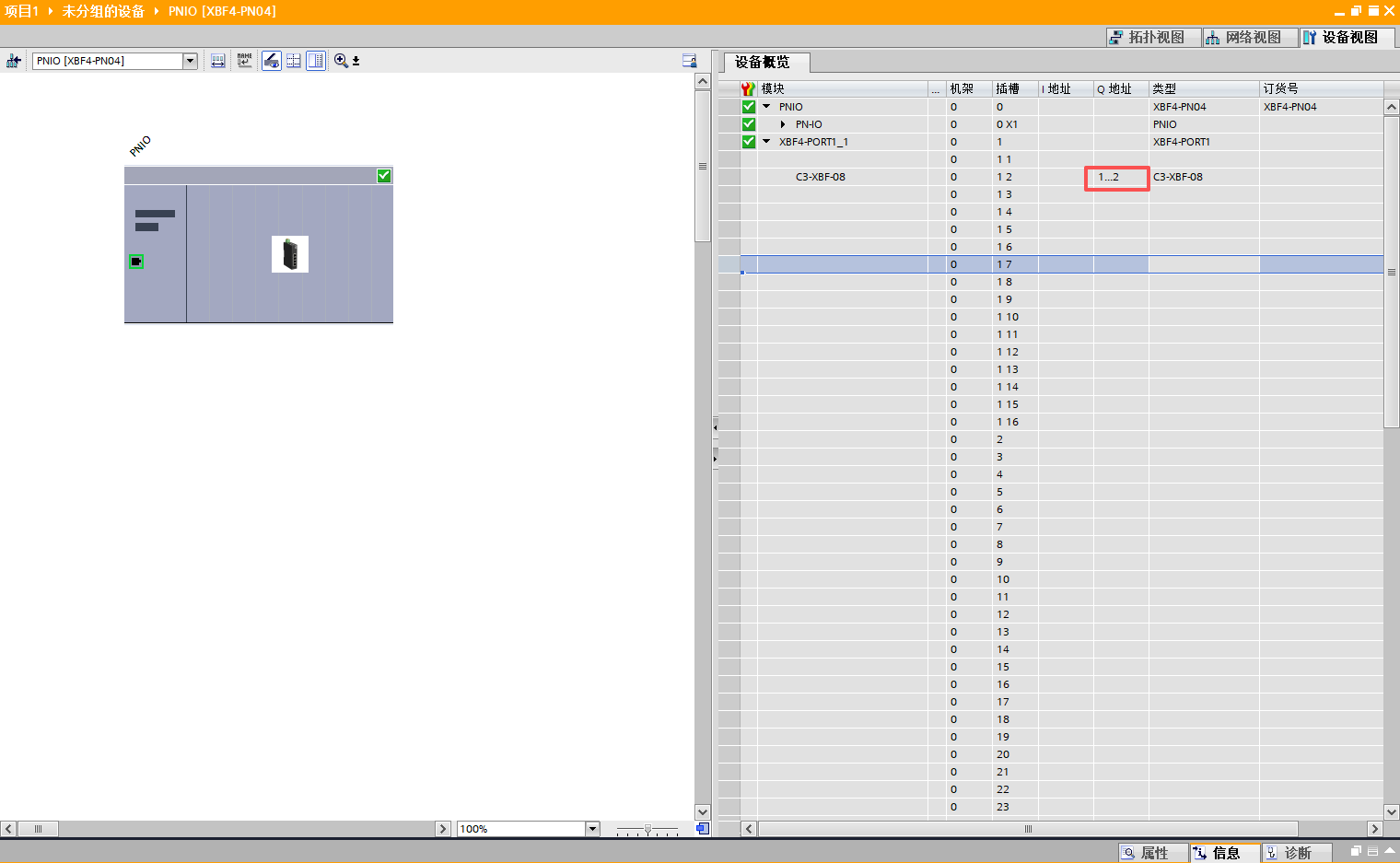
VI. Special Note
I/O addresses can be viewed in the "Device overview" of the module configuration. If you need to adjust the address range, you can manually modify the start address there.