When communication disconnection occurs on the GW6L series slice gateway, how to quickly diagnose and locate the fault
Article Overview
1. Applicable Product
GW6L Series Slice Gateway
2. Problem Scenario
Communication disconnection occurs on the gateway, requiring rapid fault diagnosis
3. Diagnostic Methods
LED status observation / Uplink input data status bit reading
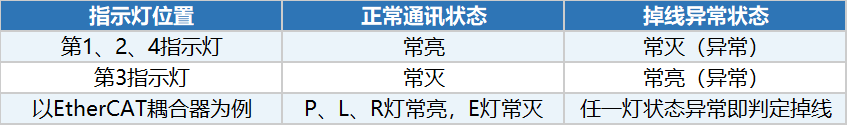
4. Normal Communication Indicators
Coupler LEDs 1, 2, 4 steady on, LED 3 steady off; status byte value = 1
5. Disconnection Judgment Basis
Abnormal LED status, or status byte value ≠ 1
When a communication disconnection occurs on the Solidot GW6L series slice gateway, how to quickly diagnose and locate the fault?
For this common issue, the GW6L series provides two basic diagnostic methods: first, directly observe the LED status on the power module and coupler panel to quickly determine whether the gateway is online; second, read the last status byte of the gateway's uplink input data to confirm the current communication status by checking whether the byte value equals 1. This article introduces the judgment basis and troubleshooting steps for both diagnostic methods.
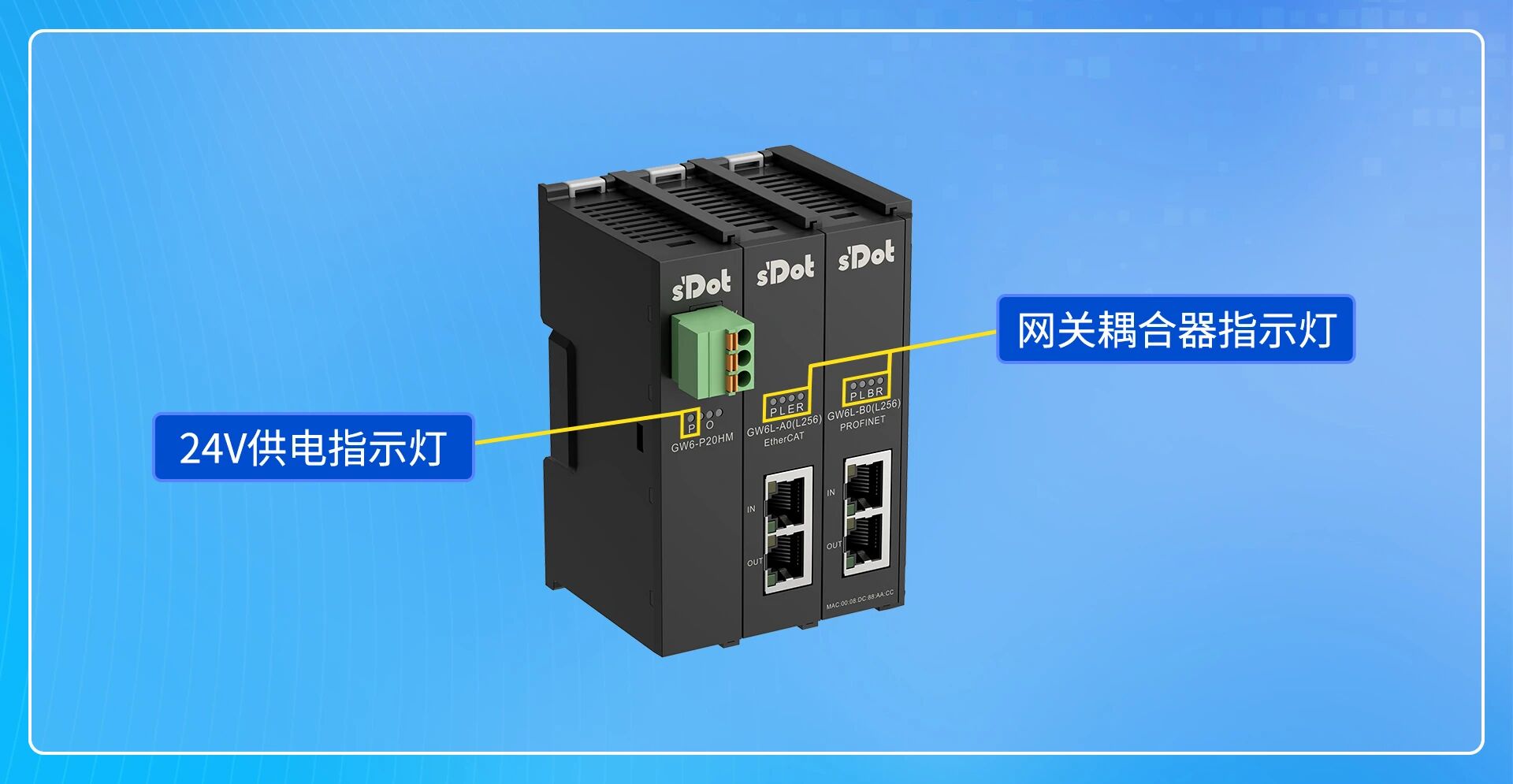
I. Locate Faults via LED Status
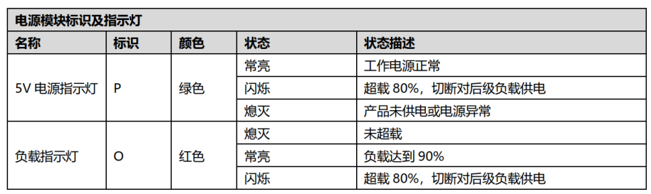
Before performing any complex operations, observing LED status is the fastest and most direct diagnostic method. The GW6L series kit power panel has 2 LEDs, and the coupler panel has 4 LEDs. Each LED corresponds to specific communication status information.
Scenario 1: Power module P LED is off
1.Check wiring: Verify that the power cables on the power module terminal block (24V and 0V) are not loose, disconnected, or poorly crimped.
2.Measure voltage: Use a multimeter in DC voltage mode to measure the voltage at the power input terminal, confirming it is within the normal operating range (DC 18–30V).
3.Determine module failure: If the input terminal voltage is normal but the P LED remains off, the gateway's internal power circuit may be damaged and require repair.
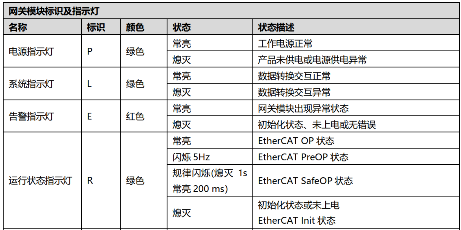
Scenario 2: Coupler LED status is abnormal
Under normal communication conditions, LEDs 1, 2, and 4 on the coupler are steady on, and LED 3 is steady off. For example, on an EtherCAT coupler, the P, L, and R LEDs are steady on, and the E LED is steady off. If any of these LEDs deviate from the normal state, the gateway is determined to be offline, and further inspection of the corresponding communication link is required.
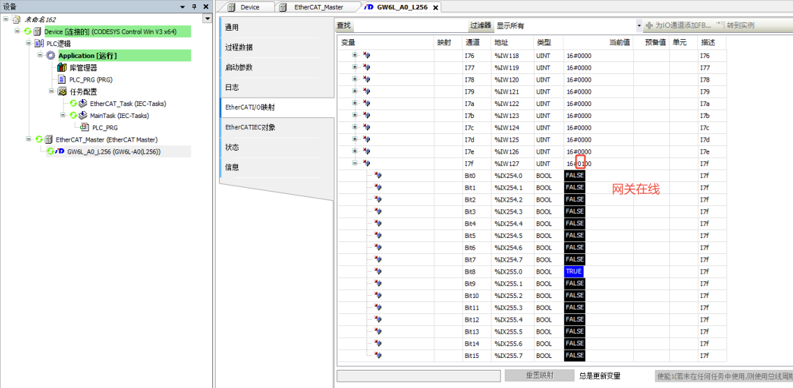
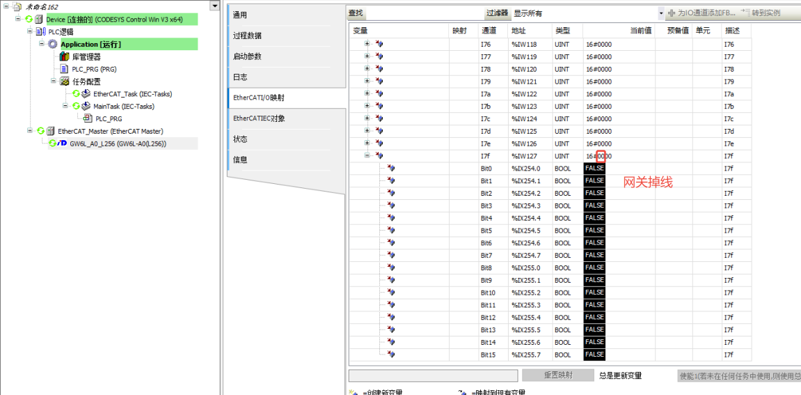
II. Locate Faults via Status Bit Reading
By reading the last byte (status byte) of the gateway's uplink input data, the communication status of the gateway can be determined at the program level:

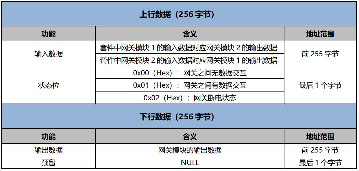
When the status byte value is 1, the gateway is in a normal online state. When the status byte value is not 1 (e.g., 0), the gateway is offline or experiencing communication anomalies. The LED status can be used together to further confirm the fault location.
Suggestion: The two diagnostic methods can be used together. LEDs are suitable for quick on-site judgment, while the status bit is suitable for automated alarms or fault logging in the program.