Knowledge

How to configure and use the slice encoder counter module XB6S-PL20 in TIA Portal
Article Overview
1. Demo Product
2. Communication Protocol
PROFINET
3. Configuration Tool
Siemens TIA Portal
4. Supported Signals
ABZ encoder signal / pulse-direction signal / dual-pulse signal
5. Functions Involved
Configuration / basic counting / probe latch (single-shot / continuous) / compare output
How to configure and use the Solidot slice 2-channel single-ended incremental encoder counter module XB6S-PL20 in TIA Portal, and use its counting, probe latch, and compare output functions?
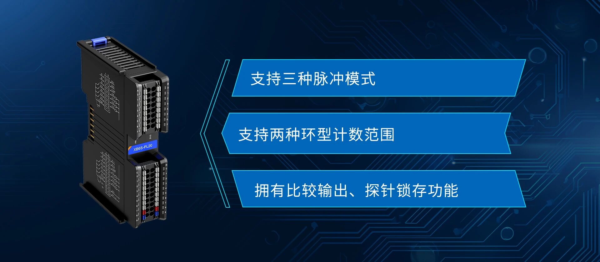
This article uses the XB6S-PL20 with the PROFINET coupler XB6S-PN2002, introducing the configuration process and the use of three functions: basic counting, probe latch, and compare output.
I. Configuration
1. Create a New Project and Add Device
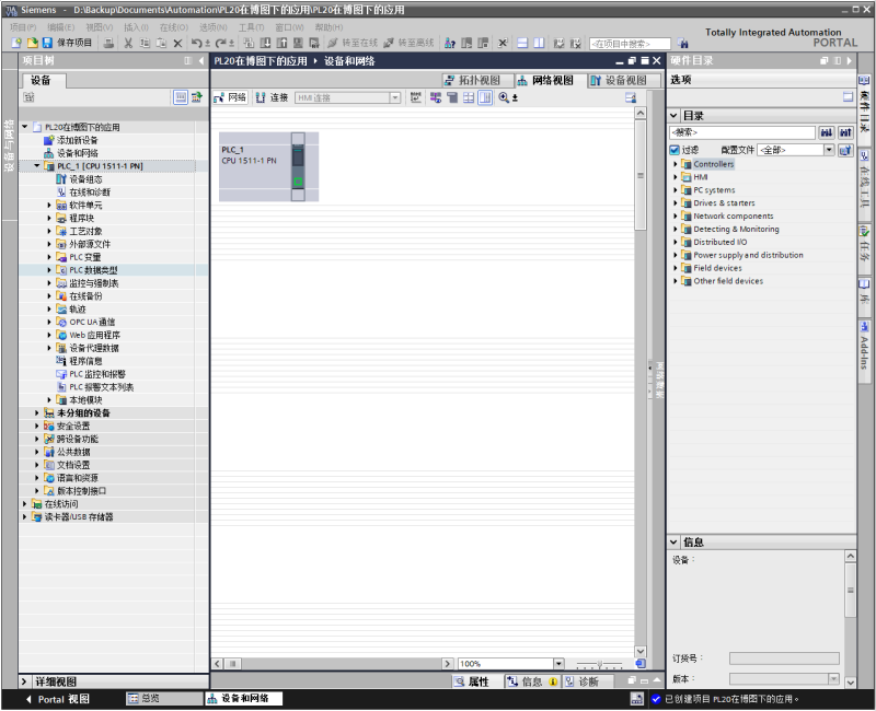
Create a new project in TIA Portal, add the PLC device according to the actual hardware, and complete the initial project creation.
2. Install GSD Configuration File
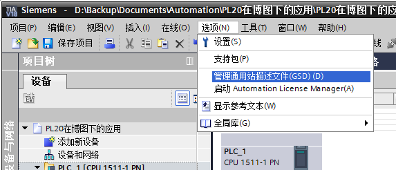
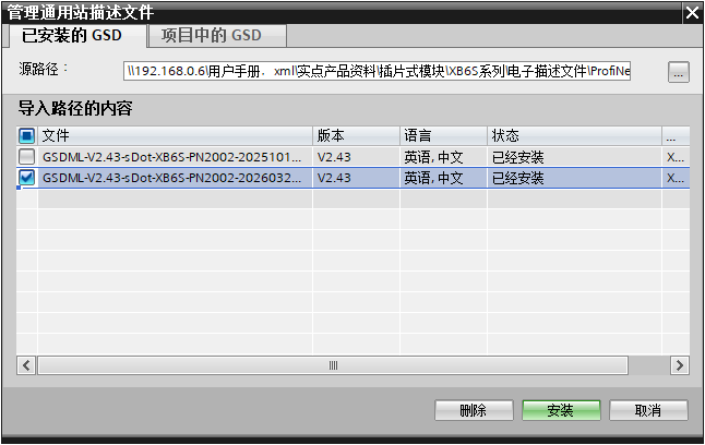
Click "Options" → "Manage general station description files (GSD)" on the TIA Portal menu bar to enter the GSD file management interface. Select the folder containing the GSD file, check the corresponding file, and click "Install" to complete the import.
3. Assign Device Name and IP Address
In the project tree, expand "Online access" → select the corresponding network card → "Update accessible devices". After scanning the coupler (factory default has no device name or IP address; the scan result shows the MAC address), click "Online & diagnostics" → "Functions" to assign the IP address and PROFINET device name.
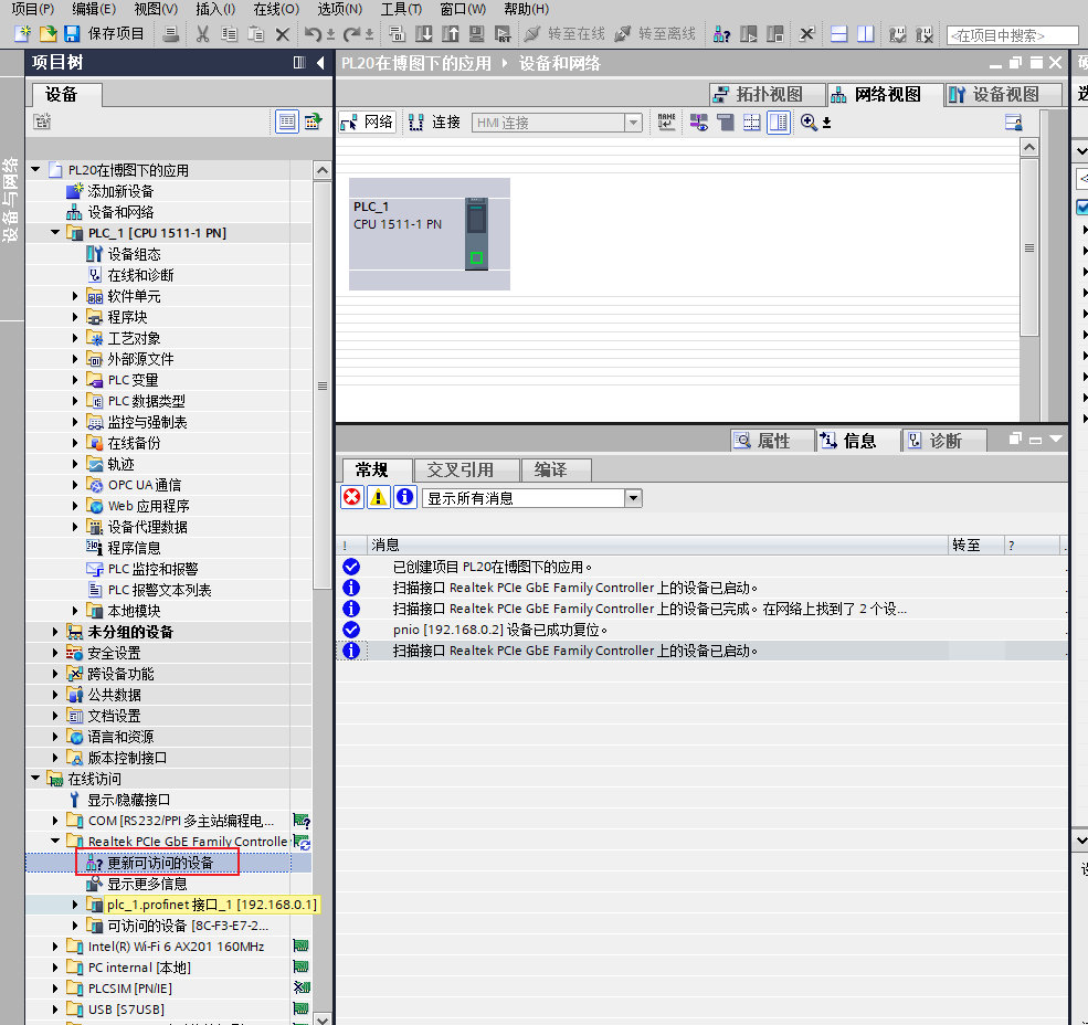
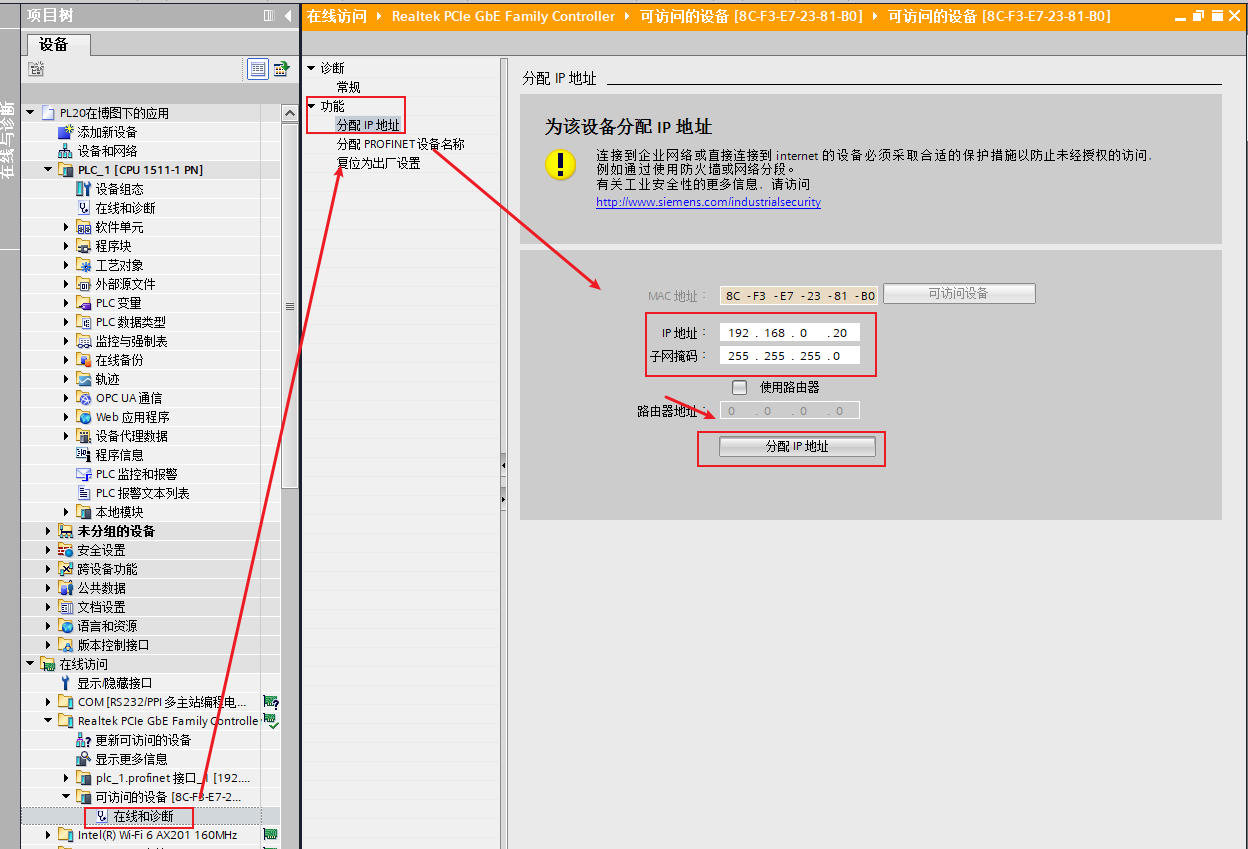
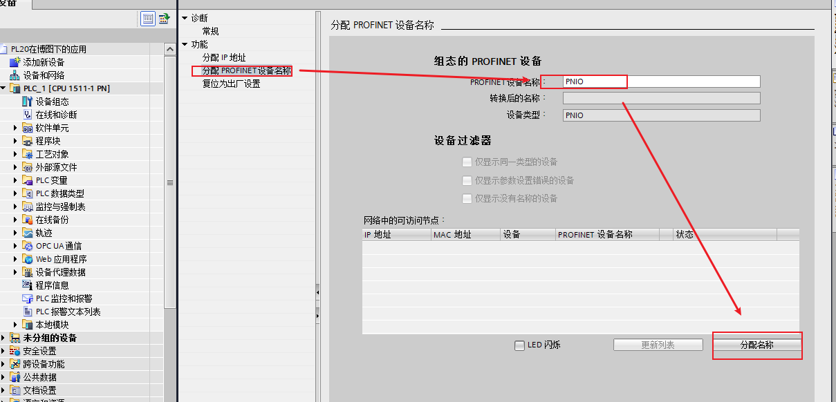
Note: The coupler has no preset device name or IP address at delivery. Manual assignment via online scan is required for first use; otherwise, it cannot be recognized by the PLC.
4. Online Hardware Detection and Download Configuration
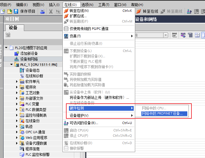
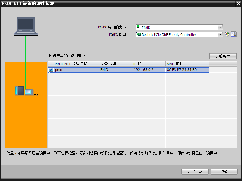
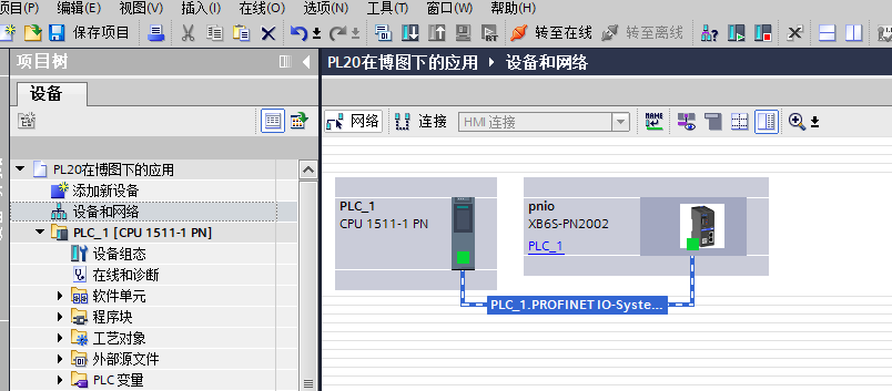
Click "Online" → "Hardware detection" → "PROFINET devices in network", click "Start search", select the coupler and add it to the PLC network. Download the hardware configuration and switch to online mode to confirm successful configuration.
II. PL20 Function Usage
1. Wiring Method and Terminal Definition
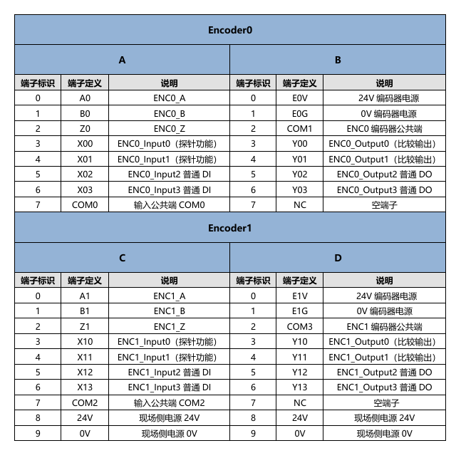
Refer to the diagram below for terminal wiring definitions. Choose the corresponding wiring method according to the actual signal type (ABZ / pulse-direction / dual-pulse).

2. Basic Counting Function
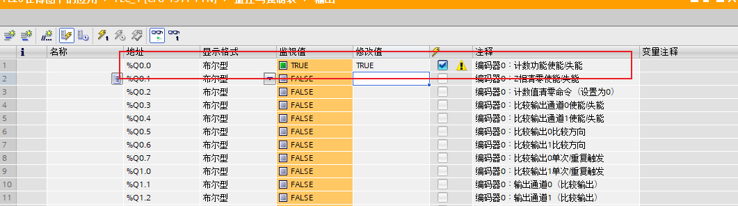
Open the coupler device view in TIA Portal, check the I/O start address of the PL20 module, confirm each variable address according to the address table, complete the wiring correctly, and enable counting to start.
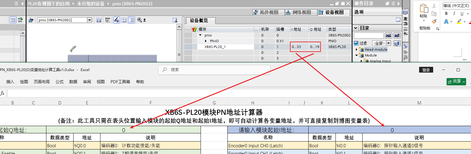
In this example, a pulse generator is used to send a pulse signal at 1000Hz for verification.

3. Probe Latch Function
PL20 has 2 probe channels per channel, supporting single-shot latch and continuous latch modes. When the probe input channel detects a valid signal, the current count value is recorded in the latch register of the corresponding channel, and the probe latch flag toggles (the trigger edge of the probe input can be configured as rising or falling edge).
This example uses single-shot rising edge trigger: turn on the input latch channel 0 enable switch, trigger a latch after the probe signal is connected, and read the current count snapshot in the corresponding latch value address.
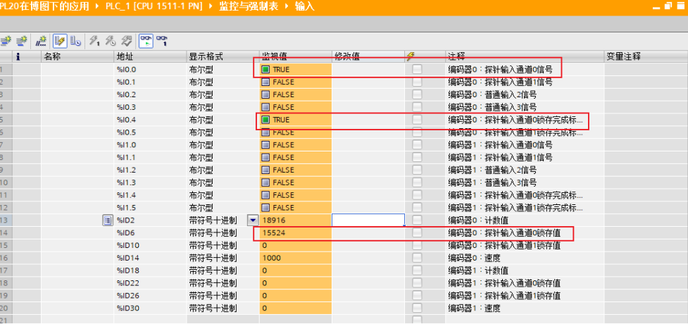
Note: Single-shot latch must be re-enabled after each trigger. In continuous latch mode, the latch value is updated on every valid signal.
4. Compare Output Function
PL20 has 2 compare output channels per channel. When the count value and compare direction meet the set conditions, the compare channel outputs a pulse signal with an adjustable time (configurable range: 1–65535ms).
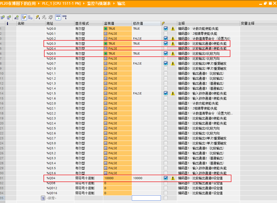
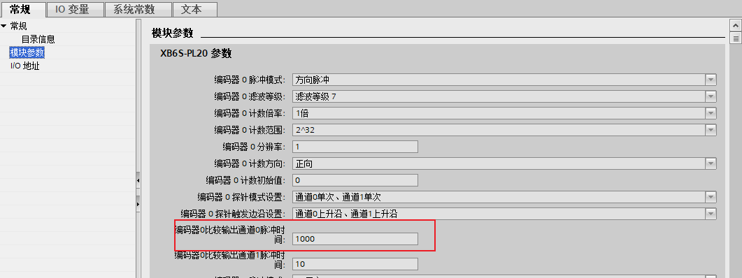
This example uses single-shot increasing comparison (count value triggers from small to large): turn on compare output channel 0 enable, set compare direction to 1 (increasing), set compare value to 10000, and output pulse time to 1000ms. When the count value increases from 0 to 10000, output channel 0 outputs a 1000ms low level, and the channel indicator stays on. After the pulse ends, it returns to high level and the indicator turns off.
Note: Compare direction 1 is increasing comparison (trigger when count value goes from small to large), direction 0 is decreasing comparison (trigger when count value goes from large to small). Choose the corresponding direction according to the actual application scenario.