How to Complete Hardware Configuration and Parameter Setting of IOL7A-A8C-M12 Analog Module in TIA Portal?
Article Overview
1. Demo Products
IOL7A-PN01B-8A + IOL7A-A8C-M12
2. Communication Protocol
PROFINET (via IO-Link Master IOL7A-PN01B-8A接入)
3. Configuration Tool
Siemens TIA Portal
4. Key Operations
Hardware configuration addition, input/output mode switching, range modification
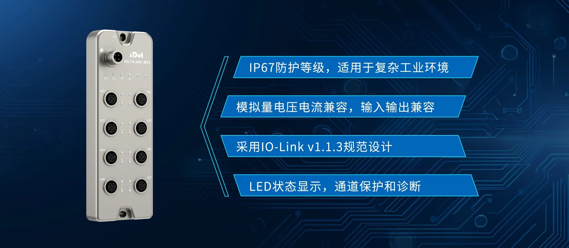
The IOL7A-A8C-M12 is a Solidot analog input/output voltage/current compatible IO-Link Hub. How to complete its hardware configuration in TIA Portal, and realize input/output mode switching and range modification?
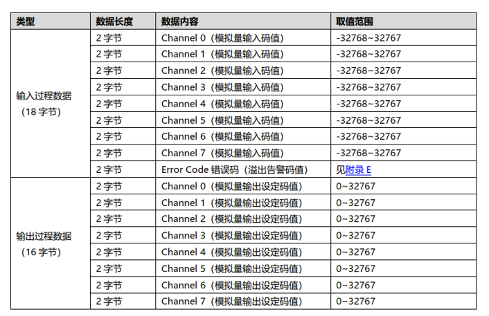
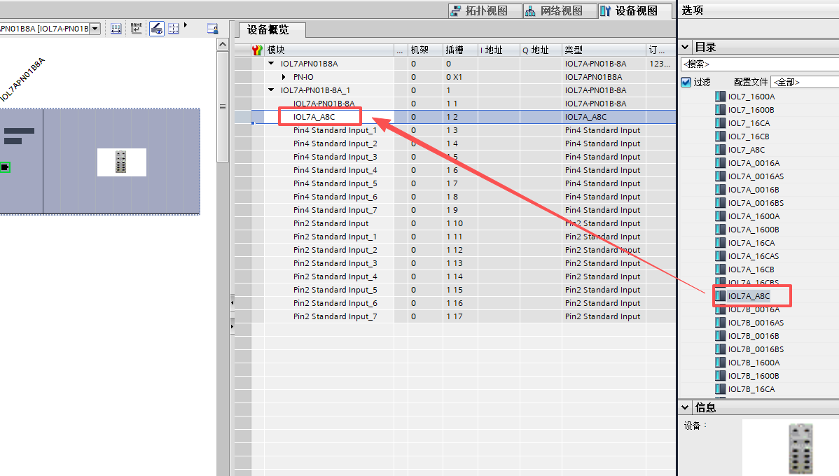
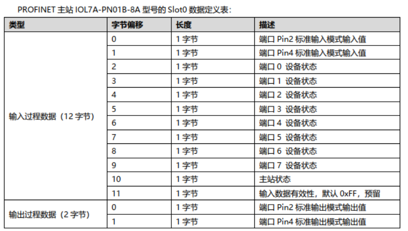
Based on its process data of 18 bytes input and 16 bytes output, we can use the IO-Link master IOL7A-PN01B-8A in TIA Portal and select the IOL_I/O_24/24byte submodule (Note: if using device description file version 20260311 or later, you can directly select the module type IOL7A-A8C-M12) to complete the configuration. This article also introduces the complete operation process including communication status confirmation, analog input testing, mode switching, and range modification.
I. Hardware Configuration Addition
STEP 1
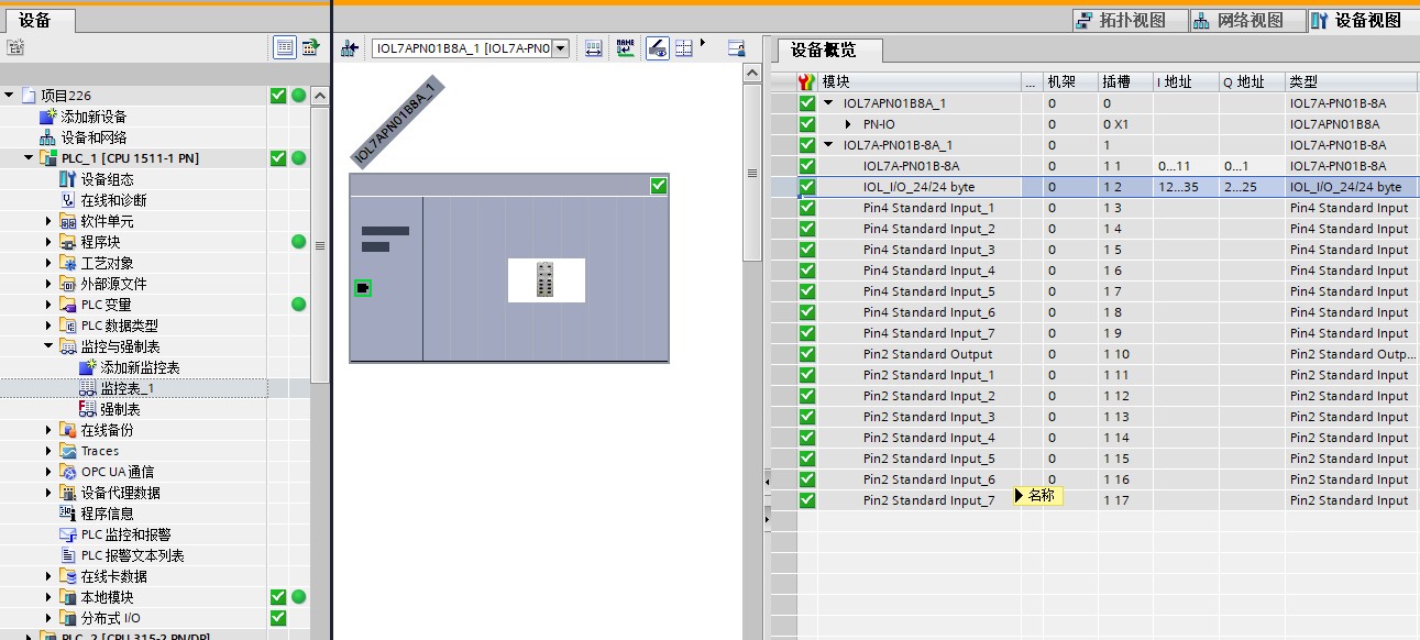
In TIA Portal hardware catalog, find the IO-Link master IOL7A-PN01B-8A and add it to the configuration. After adding the master, definitions for PIN4 and PIN2 of 8 ports are generated by default, all with type Standard Input.
STEP 2
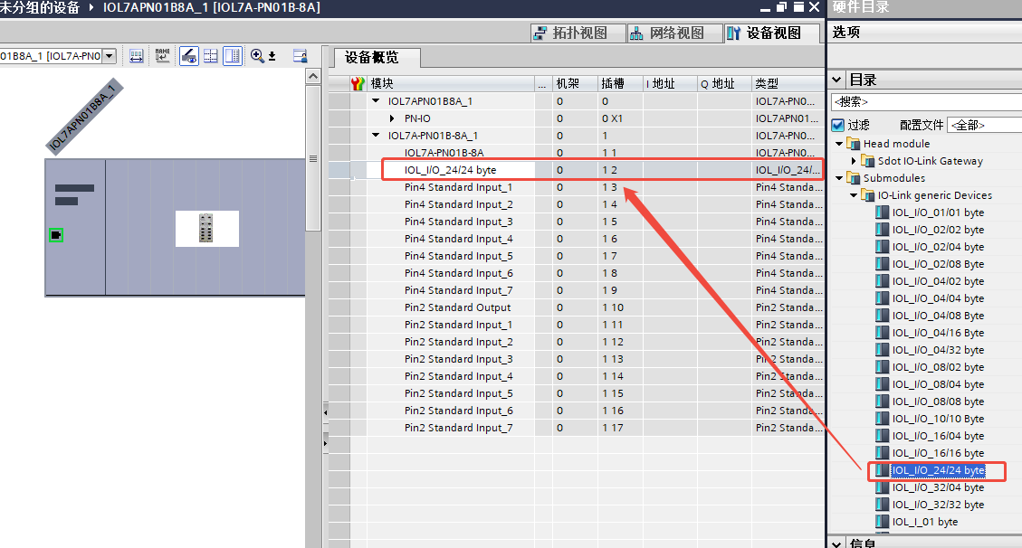
Right-click to delete the default PIN4 port definition, and select IOL_I/O_24/24byte (Note: if using device description file version 20260311 or later, you can directly select the module type IOL7A-A8C-M12) to complete the submodule configuration addition.
II. PROFINET Master Data Definition
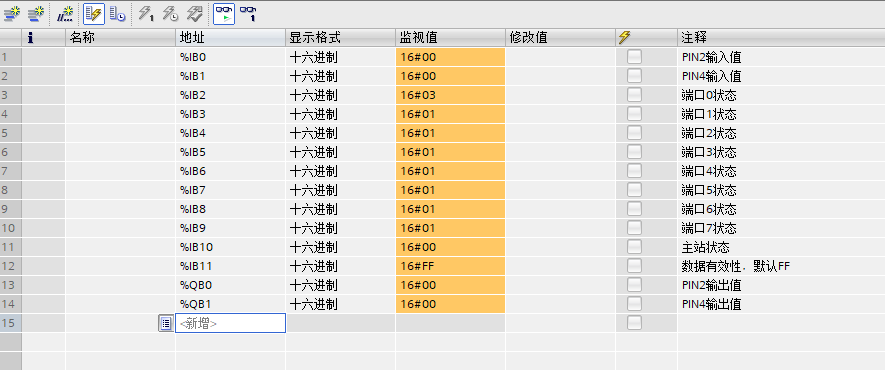
After configuration, monitor the value of %IB2 online. According to the definition table, when %IB2 = 16#03, it indicates that port 0 has been successfully configured in IO-Link mode and communication is normal.
III. Analog Input Test
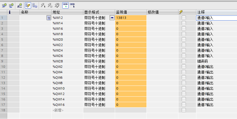
The IOL7A-A8C-M12 is default configured as analog input mode with range 0–10V, corresponding to numerical range 0–27648.
Test method: Apply a 5V voltage signal to X00 and monitor variable %IW12 online.
Test result: %IW12 reads 13813, theoretical value 13824, deviation within allowable accuracy; analog input function is normal.
IV. Analog Input/Output Mode Switching
Configuration entry: Right-click IOL_I/O_24/24byte, select "Properties", enter the module parameter configuration interface.
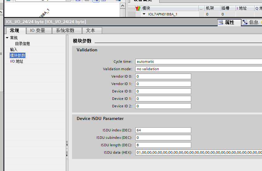
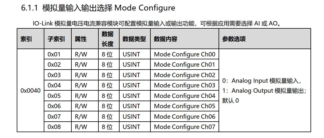
Configuration example: Switch X00 to output mode, keep X01–X07 in input mode. Write the following parameters:
Index: 64
Subindex: 0
Length: 8
Data: 01,00,00,00,00,00,00,00
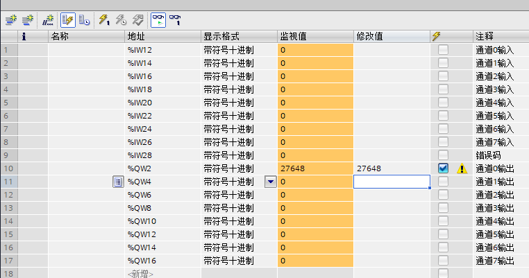
Download and test: Switch to offline mode and download hardware configuration. Assign 27648 to %QW2, measure 10V output at the module output terminal; mode switching function is verified normal.
V. Analog Range Modification
Configuration entry: Right-click IOL_I/O_24/24byte, select "Properties", enter the module parameter configuration interface.
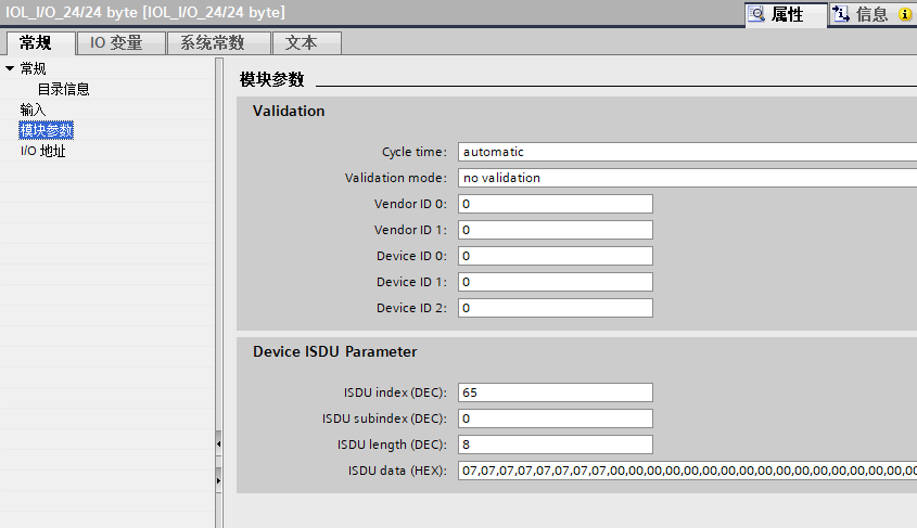
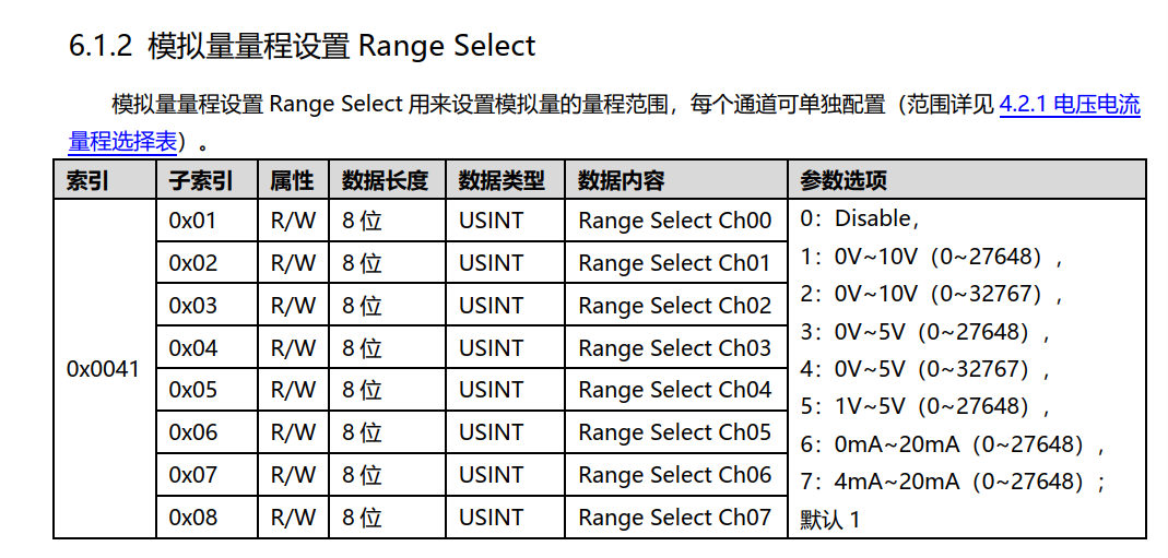
Configuration example: Switch the range of all 8 channels X00–X07 to 4–20mA (corresponding numerical range 0–27648). Write the following parameters:
Index: 65
Subindex: 0
Length: 8
Data: 07,07,07,07,07,07,07,07
Download: Switch to offline mode and download hardware configuration; the range modification takes effect.
VI. Key Operation Notes
1.Module configuration requires first deleting the master's default port definitions, then adding the IOL_I/O_24/24byte submodule.
2.After mode switching and range modification, you must switch to offline mode and re-download the hardware configuration; otherwise, the parameters will not take effect.
3.Default range is 0–10V, corresponding to values 0–27648. To use other ranges, you need to configure and download the corresponding parameters for Index 65 via ISDU.