Solidot Modbus TCP Protocol Coupler XB6S-MT2002 Quick Start Guide
Article Overview
1. Demo Product
Modbus TCP Protocol Coupler XB6S-MT2002+ Loaded Slice I/O Modules
2. Communication Protocol
Modbus TCP
3. Configuration Tool
Web browser (built-in Web configuration interface, no additional software required)
4. Compatible Master
Supports standard Modbus TCP masters (PLC/HMI/SCADA, etc.)
5. Configuration Result
Digital/analog I/O data mapped to Modbus TCP registers for read/write control
The XB6S-MT2002 is a Solidot Modbus TCP protocol coupler that supports expansion of various slice modules including digital input/output, analog input/output, high-speed pulse counting, and serial communication. This article details the complete operation process for network parameter configuration, module parameter settings, and data address query, allowing users to get started quickly.
I. Configure Coupler Parameters via Network
Enter the module's default IP address 192.168.1.120 in the browser address bar to access the coupler's Web configuration interface.
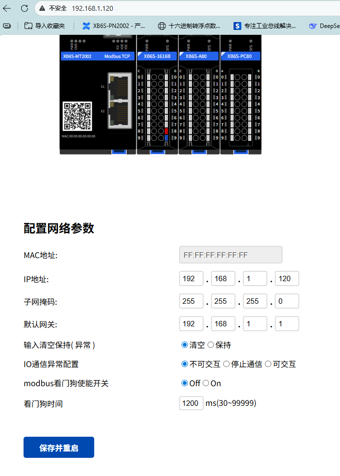
Parameter descriptions in the Web interface are as follows:
IP Address: After updating the IP address in the Web interface, click "Save and Restart". The new IP address takes effect after the restart is complete.
Input Clear/Hold (Error) and I/O Communication Error Configuration: Used to configure how input data is handled when an error occurs with the coupler's loaded I/O modules (e.g., module damage, loose installation causing backplane bus communication errors). Select "Clear" to zero the data, or "Hold" to retain the last valid data.
Modbus Watchdog Enable: When the master does not send a request message within the set watchdog time, the module will determine a timeout and automatically disconnect. This function can be manually disabled.
II. Change Parameters of Loaded Slice I/O Modules
In the Web interface, click on the corresponding module to enter its I/O parameter configuration interface. The example below shows changing configuration parameters of XB6S-1616B and XB6S-A80.
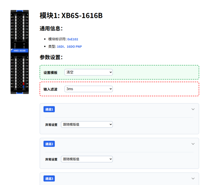
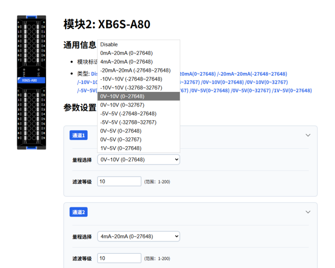
After changing parameters, click "Submit" to apply. Parameter changes take effect online without restarting the device.
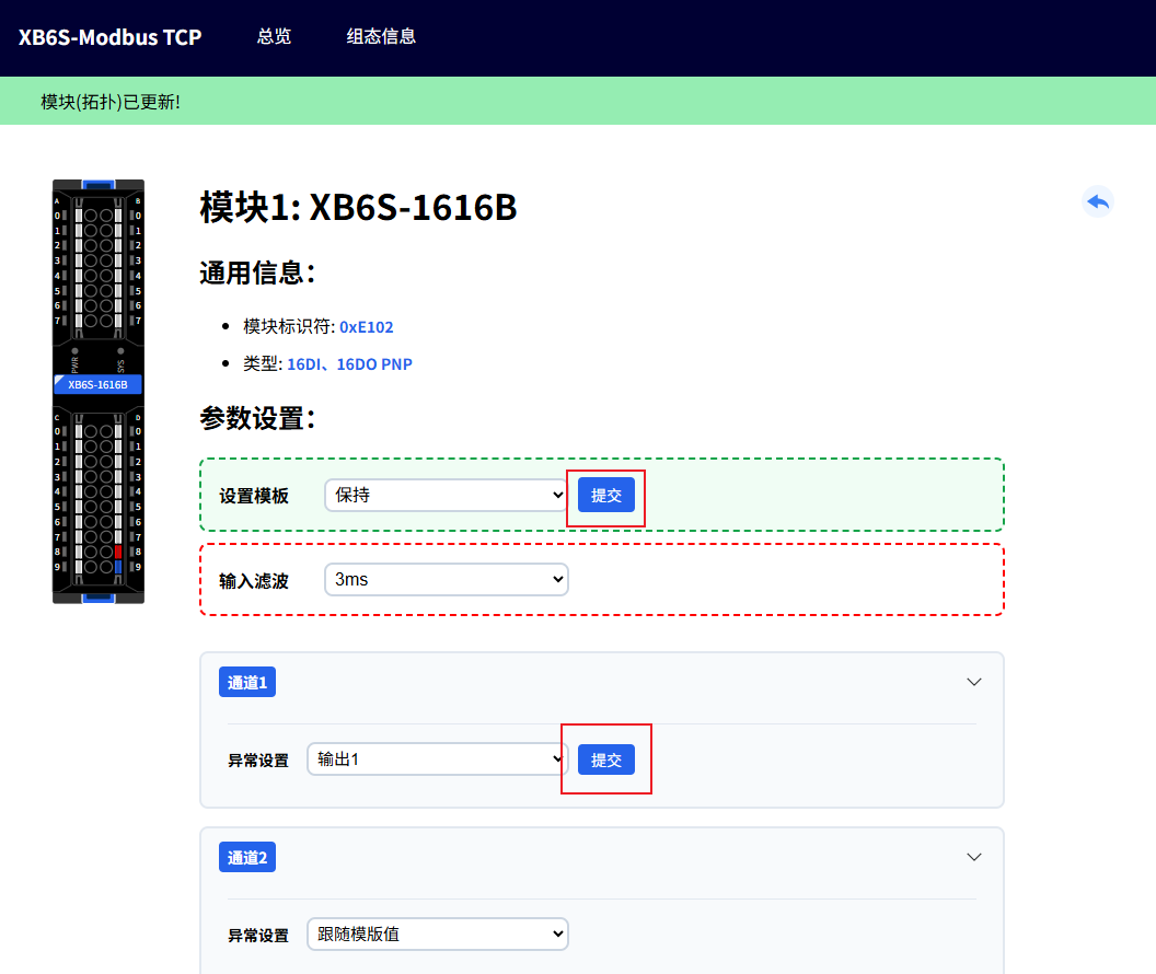
Note: Disconnect all Modbus master connections before changing parameters.
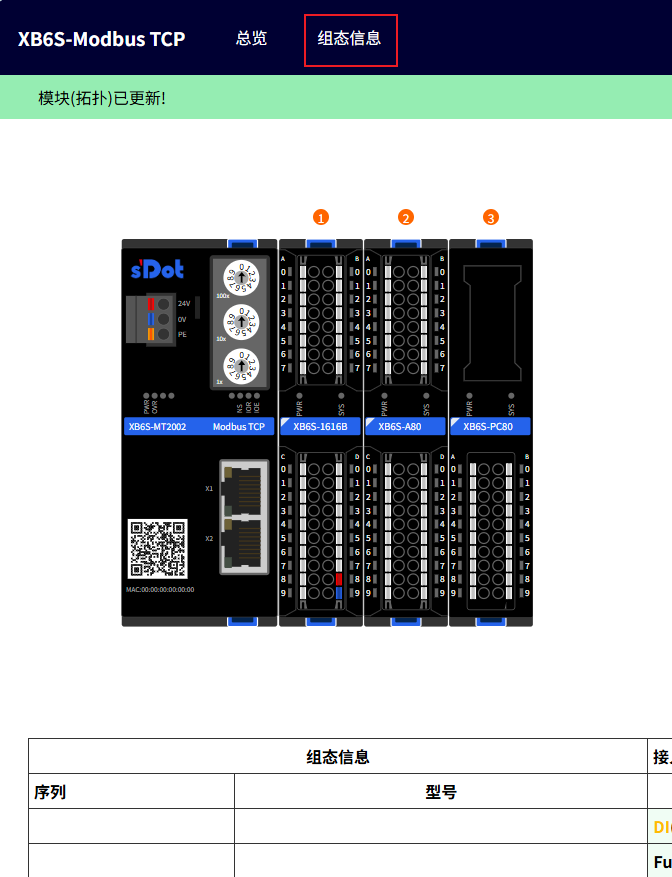
III. View Input/Output Function Codes and Data Addresses
Slice I/O modules support flexible combinations. Data addresses are automatically arranged in the order of DI, DO, AI, AO. To query the data address of a specific module, view it on the "Configuration Information" page.
Address assignment and function codes for this example are as follows:
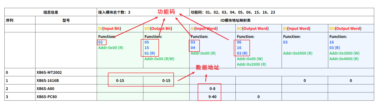
Addr: Data offset start address
(R) indicates read function, including DI/AI data reading and DO/AO actual output readback
(W) indicates control output function