Knowledge

How to troubleshoot when XB6S-EC2002 has no output response under CODESYS platform
Article Overview
1. Applicable Products
XB6S-EC2002+ XB6S Digital Output Module (using XB6S-1616A as an example)
2. Platform
CODESYS Platform
3. Problem Scenario
Output command is present in the program, but the module channel indicator does not light up, and the actual actuator does not respond
4. Troubleshooting Dimensions
Check diagnostic information / Check load power supply / Check variable address occupation / Direct assignment test in I/O mapping area
5. Troubleshooting Entry Point
First check whether the channel indicator lights up, then follow the troubleshooting sequence step by step
When using the Solidot Slice I/O EtherCAT protocol coupler XB6S-EC2002 with a digital output module on the CODESYS platform, if an output command has been issued in the program but the module channel indicator does not light up and the actual actuator does not respond, how should you troubleshoot?
This issue can generally be located from four dimensions: check the coupler diagnostic history to confirm whether the load power supply is connected, use a multimeter to verify the load power supply voltage, check whether the variable address bound to the output channel is occupied by multiple coils, and perform an output isolation test by directly assigning a value in the I/O mapping area. This article uses the XB6S-EC2002+XB6S-1616A combination as an example (Note: the test environment also includes an XB6S-A08V, but the troubleshooting does not involve that module), explaining each step in detail.
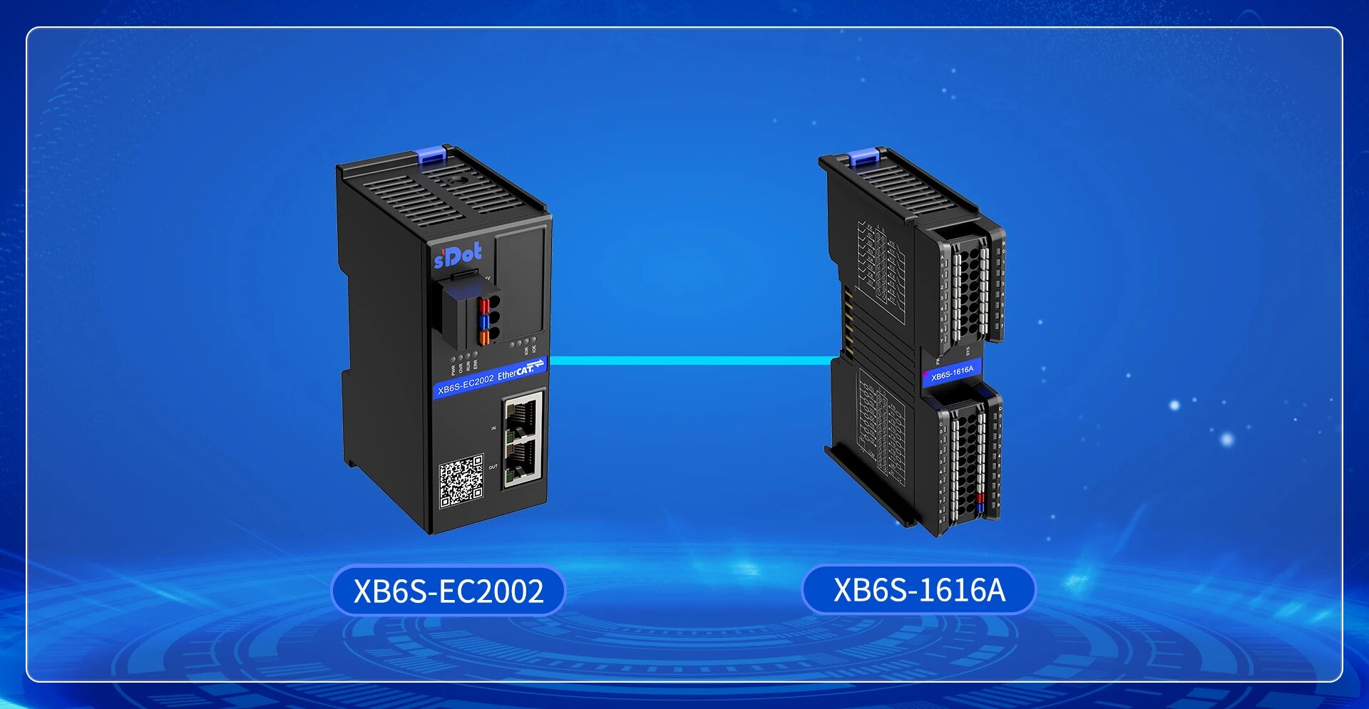
Pre-judgment: Before troubleshooting, observe the indicator status of the corresponding channel. If the indicator lights up but the actuator does not respond, first check the wiring. If the indicator does not light up, follow the steps below.
I. Check Coupler Diagnostic Information
Fault feature: A red exclamation mark appears on the coupler icon.
Click the coupler and select "Diagnostic History". Check whether there is an error message such as "First module: Load power not connected". Take XB6S-1616A as an example; looking at its wiring diagram, terminals D8/D9 of this module require an external 24V to power the load of the output channel. If this terminal is not wired, even if the program sends an output command, the channel indicator will not light up, and no voltage will be output at the output port.
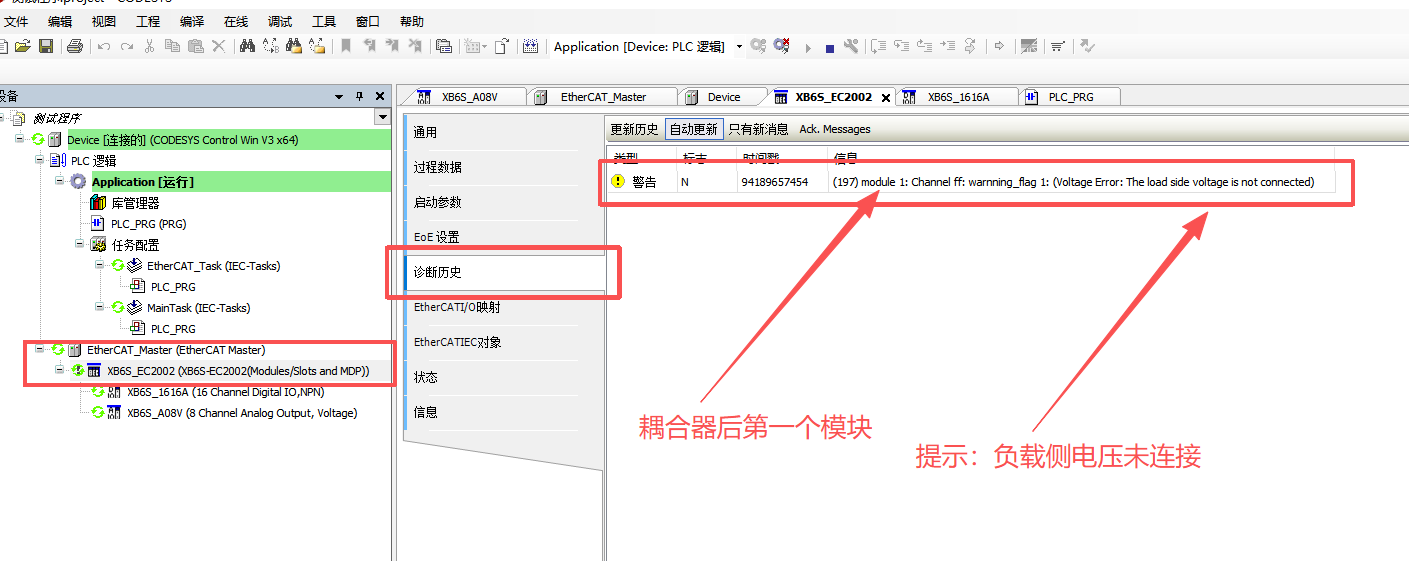

Note: The load power supply terminals (D8/D9) and the module operating power supply are independent. Both must be correctly wired for the output function to work properly.
II. Check Whether the Load Power Supply is Normal
Fault feature: Terminals D8/D9 are wired, but the output channel still does not respond.
After confirming that D8/D9 are wired, use a multimeter in DC voltage mode to measure the actual voltage at terminals D8/D9. Check the following:
Whether the voltage is within the normal range (DC24V)
Whether the polarity is correct (exclude reverse connection)
Whether the terminal crimp is secure (exclude loose connection)
III. Check Whether the Variable Address is Occupied by Multiple Coils
Fault feature: External power supply is normal, but the output value cannot be monitored either in the I/O mapping or in the program.
If the variable bound to the output channel (e.g., TEST2) is called by multiple coils in the program, the compilation will not produce an error, but at runtime, the status of other coils will overwrite the output value of that variable, causing the expected output to not be correctly issued. You need to unbind the variable from other coils, or rebind the output channel to a variable address that is not used by other program sections.
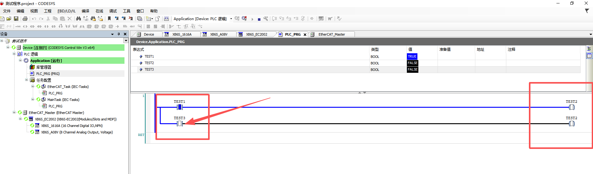

Tip: The multiple coil problem does not cause a compilation error in CODESYS; you must actively check the call relationships of variables section by section. Use the "Cross Reference" function to quickly locate all locations where the variable is called.
IV. Direct Assignment Test in I/O Mapping Area
If none of the above checks reveals an abnormality, you can further isolate the fault location using the following method.
Directly assign a value to the target channel in the I/O mapping area, bypassing the program logic, and observe the indicator status of the corresponding channel. Based on the results, handle in two directions:
Indicator lights up, actuator does not respond → The output signal has been correctly issued; the problem is on the wiring side. Check whether the wiring on the actuator side is correct.
Indicator lights up, actuator responds → The module output function is normal; the problem is on the program logic side. Further check whether there are multiple coils or logic overwriting in the program.