How to define process data addresses for XB6S-C01SP in Modbus master mode?
Article Overview
1. Applicable Product
2. Communication Protocol
Modbus (Master Mode)
3. Core Issue
Differences in process data addresses when Control Mode is set to Disable vs. Level
4. Key Impact
When control word is enabled (Level mode), TX/RX addresses shift overall, requiring reserved addresses for control word, status word, and alarm code
5. Prerequisite
The client is already able to properly configure and use the XB6S-C01SP module
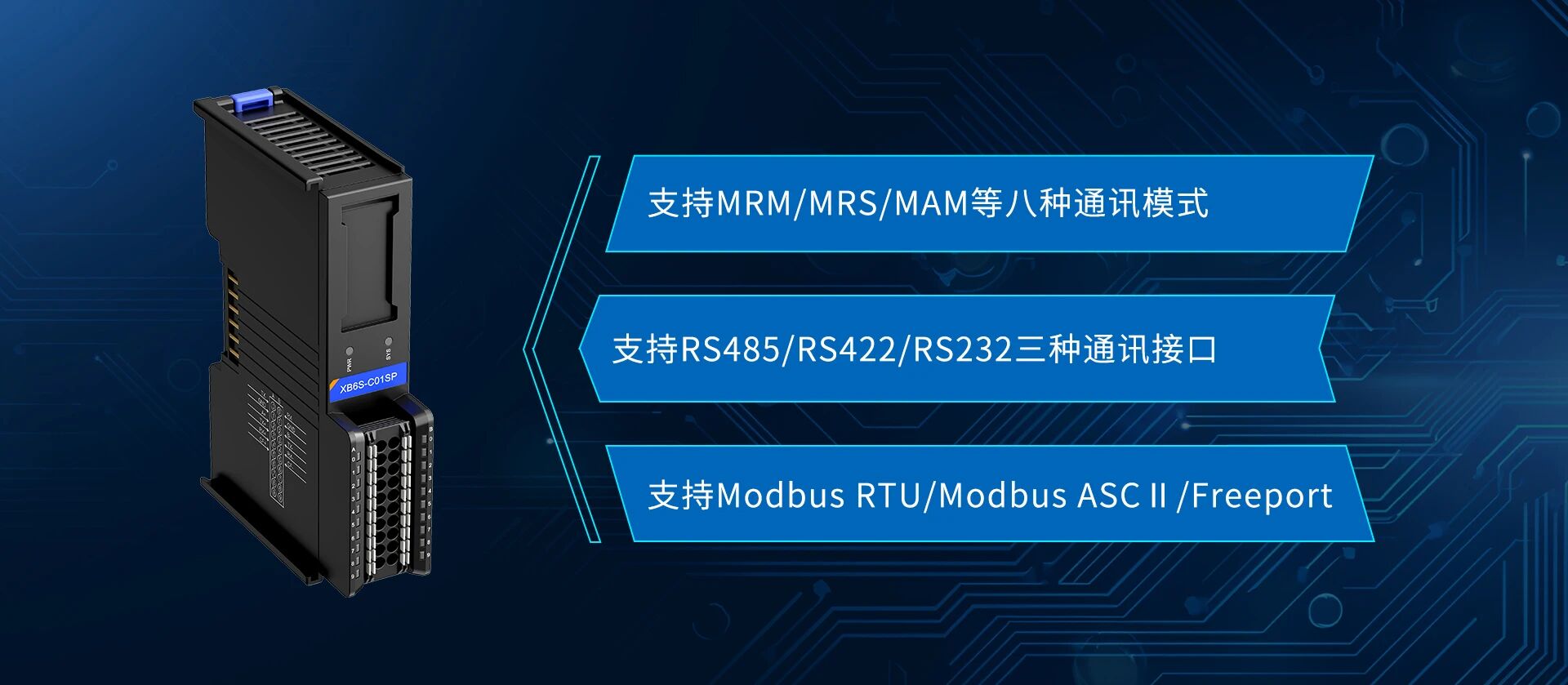
The XB6S-C01SP is a Solidot Slice 1-channel serial communication module. How should its process data addresses be defined in Modbus master mode?
The core of this issue lies in the setting of the Control Mode parameter. When Control Mode is set to Disable (control word disabled), TX/RX process data addresses are arranged consecutively from the starting position. When Control Mode is set to Level (control word enabled), the enable control word, communication status word, and alarm code for each node occupy the front addresses of TX and RX respectively, causing the actual data addresses to shift backward. This article uses configuration examples combined with process data address mapping tables to explain the address definition rules for both modes.
Prerequisite note: This article assumes the client is already able to properly configure and use the XB6S-C01SP module; initial commissioning steps are not covered.
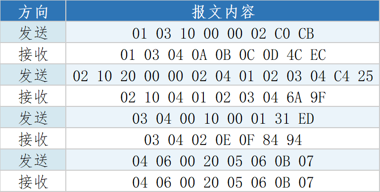
1. Modbus Master Communication Message Example
The following are examples of messages to be sent by the Modbus master and responses from the slave during configuration, for debugging and checking communication status:
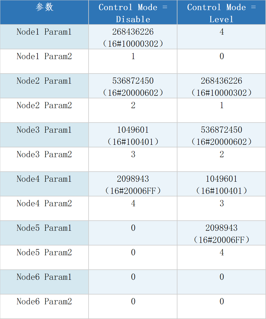
2. Node Param Configuration Comparison
Depending on the Control Mode setting, the Node Param parameter values differ. The table below lists the Param1 and Param2 configuration values for each node in the two modes for reference:
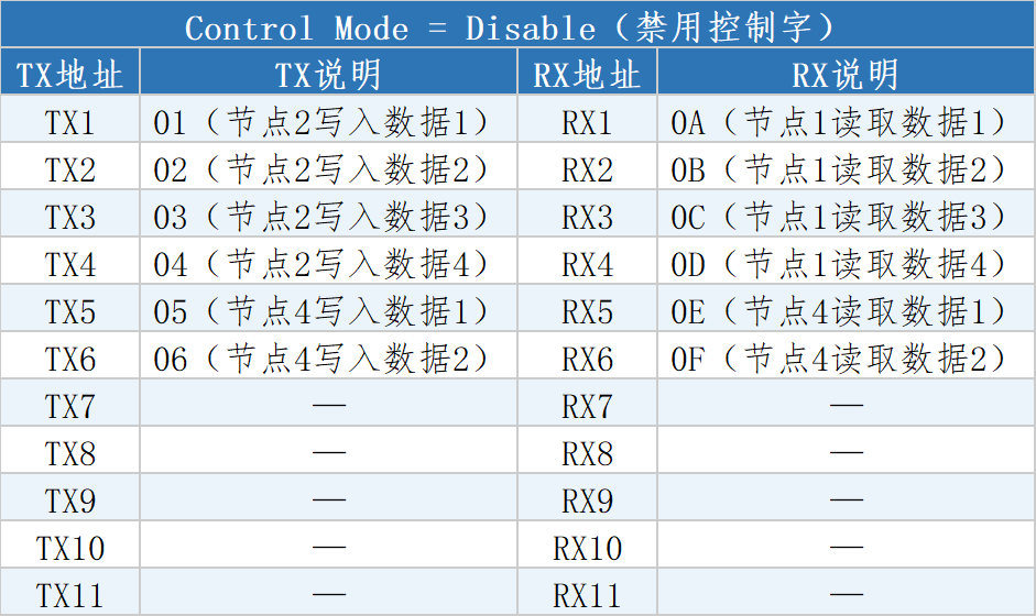
3. Process Data Address Definition
Control Mode = Disable
When control word is disabled, TX and RX process data addresses are arranged consecutively from the starting address, with no extra control word, status word, or alarm code occupying space:
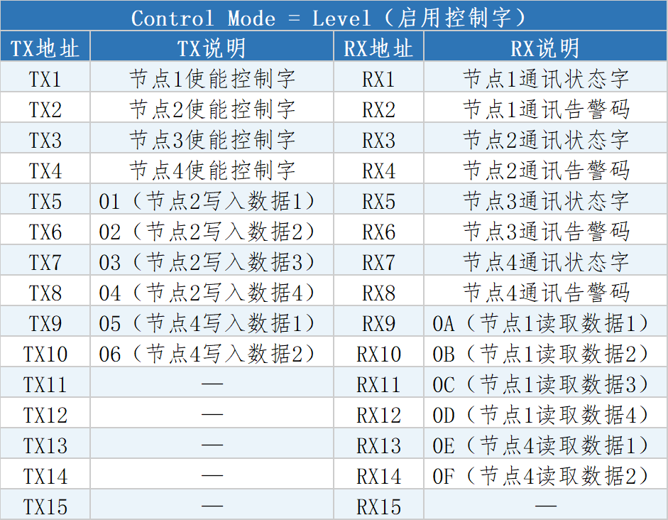
Control Mode = Level
When control word is enabled, the enable control words for each node (TX1–TX4) are arranged first in the TX process data front, and the communication status words and alarm codes for each node (RX1–RX8) are arranged first in the RX process data front, causing actual data addresses to shift backward:
4. Address Arrangement Rules
By comparing the two process data address tables above, the following rules can be summarized:
Address arrangement order follows the node configuration order, incrementing sequentially.
When control word is enabled (Level mode), enable control words are placed at the front of TX process data.
When control word is enabled (Level mode), communication status words and alarm codes are placed at the front of RX process data.
When control word is disabled (Disable mode), TX/RX addresses contain only actual data for each node, with no extra occupancy.