Knowledge

Corresponding relationship of slave addresses related toCC-link IE FieldBasic protocol
1. During the on-site project implementation, some technicians were unclear about the address arrangement of the slave stations related to the CC-Link IE Field Basic protocol, which would cause the I/O points to be misplaced and repeated rework would waste time. In fact, in the device tree of the CC-Link IE Field Basic protocol, the addresses of each slave station have been clearly divided.
For example, the configuration shown in the figure below uses Q03UDV with 8 remote I/O devices (GX Works2)——
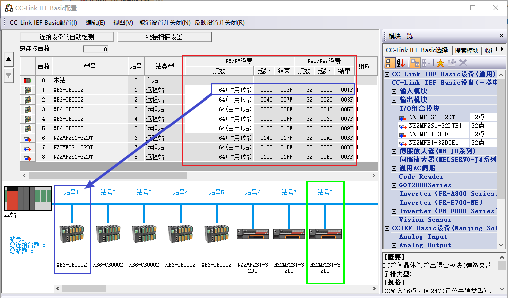
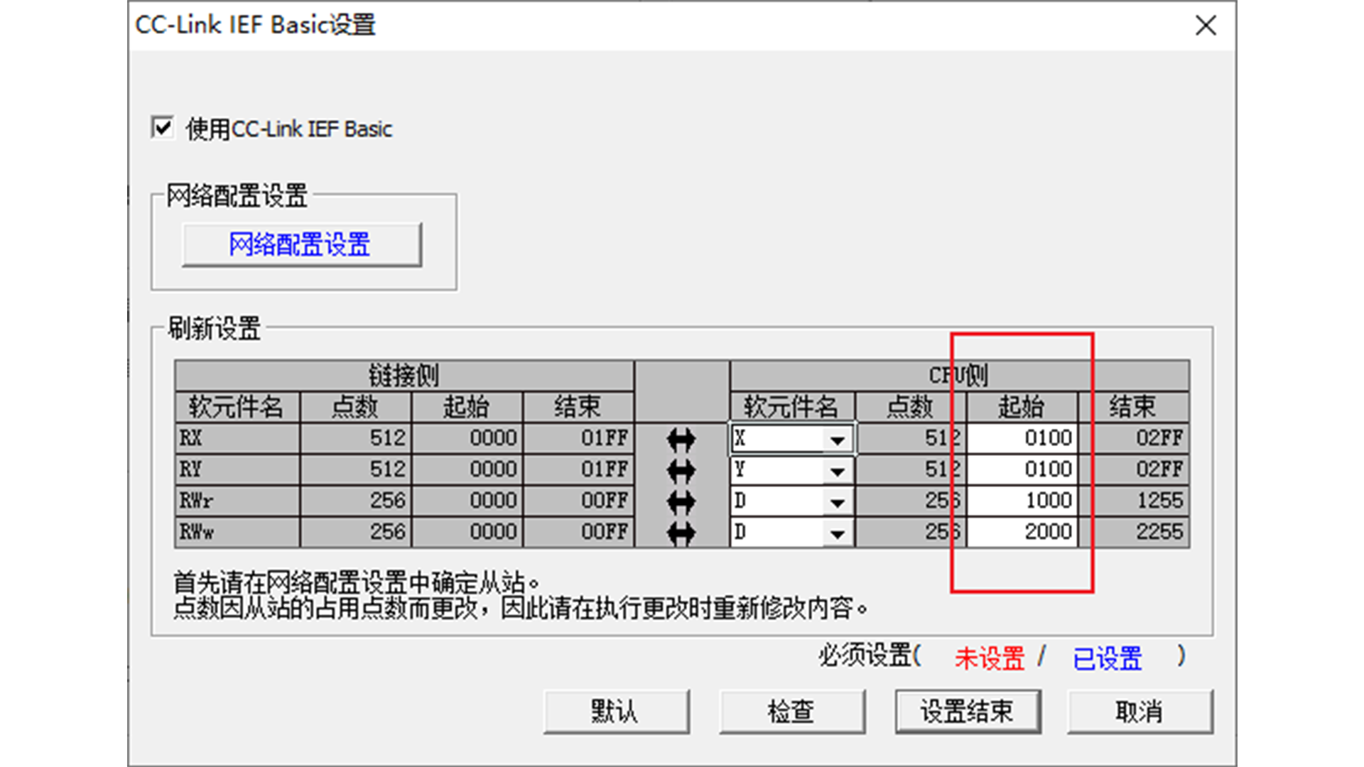
2. You can see that there are two addresses, start and end, in the two lists of "RX/RY Settings" and "RWw/RWr Settings". Each line corresponds to the start and end addresses of the slave station. In GX Works2 and GX Works3, the address here is hexadecimal and cannot be changed. The address here is combined with the manually set start address to get the actual mapping address of the slave station——
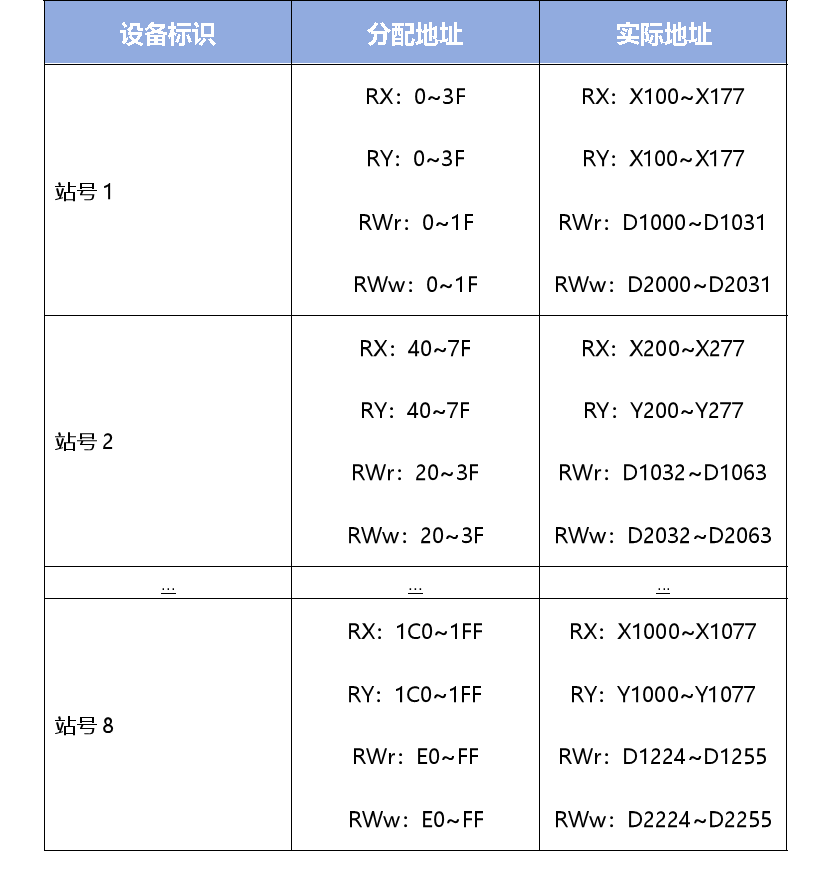
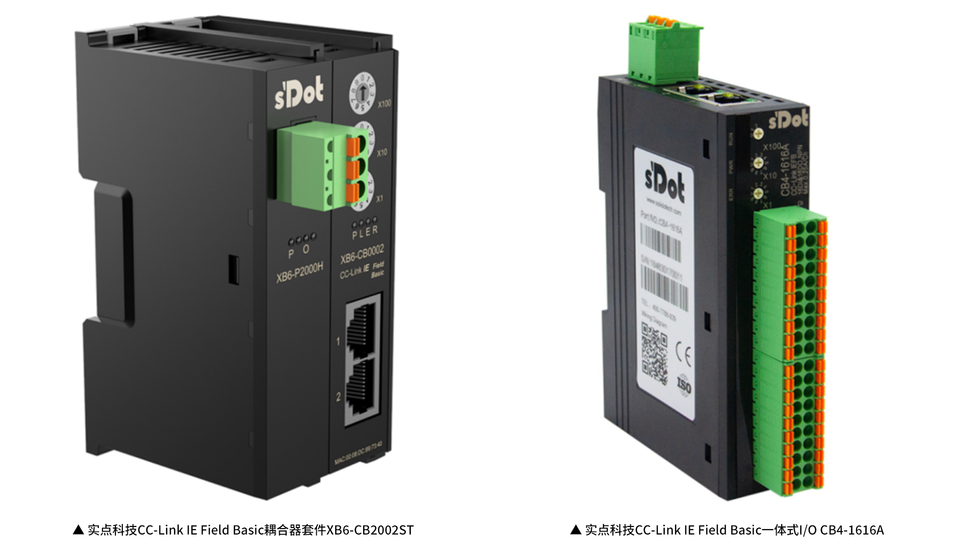
It should be noted that in this use case, the remote station occupies 1 station. The real point technology remote I/O can be configured to occupy 1~4 stations. When the number of occupied stations is greater than 1 station, the start and end addresses of the subsequent stations will also change together. If there are reserved stations in the middle, the actual mapping address will be directly reserved, and the address of the next actual station will be arranged after the reserved station. Therefore, the actual mapping address in this example is——
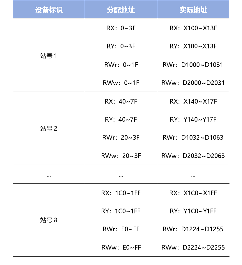
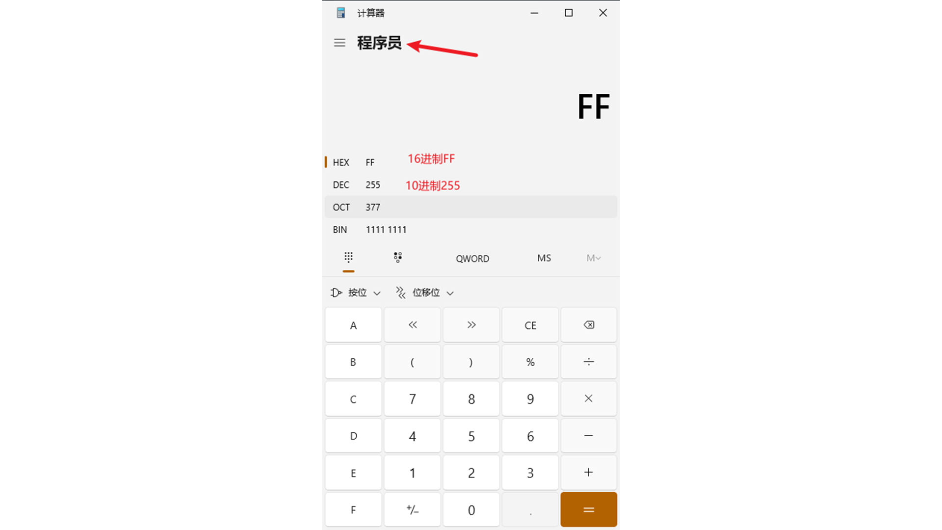
3. In addition, the data type D is decimal. When converting the RWr and RWw addresses, you need to convert the base. You can use the calculator that comes with win10 to calculate——
Similarly, the Mitsubishi FX5U address RX/RY is octal, which also needs to be converted when calculating. Therefore, when using Mitsubishi FX5U, the address is as follows——