Knowledge

How to diagnose when IO-Link slave cannot be connected
byIOL7-EC01B-8A+TwinCAT3 as an example, after adding the IOL7 master module, as shown in the figure
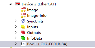
After expanding, you can see the TxPDO IO-Link Status column
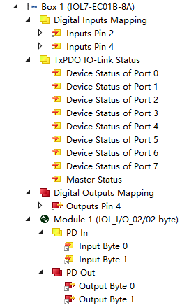
Here we first introduce the 8 ports of the main station.Taking Port0 as an example, there are 5 female connectors, PIN1 is 24V+, PIN3 is 0V, which can provide 24V power for IO-Link slaves, sensors, etc. PIN4 supports DI/DO/IO-LINK modes, while PIN2 only supports DI mode.
When the PORT port is configured in IO-Link mode, the port status can be monitored here. The IO-Link port status is represented by 1 byte, where Bit0...3 represents the IO-Link port status and Bit4...7 represents the IO-Link port error prompt. When the master station has been successfully connected, diagnostic information can be easily obtained by monitoring the data here.
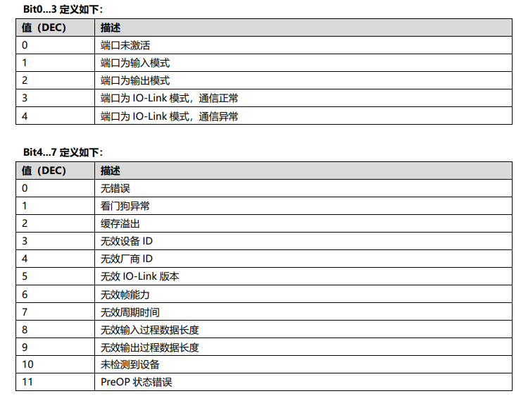
Example: The port is configured in IO-Link mode, but the slave is not actually connected, and the status prompt is 0xA4. The port is configured in IO-Link mode, but the input process data length does not match, and the status prompt is 0x84. The port is configured in IO-Link mode and is successfully connected, and the status prompt is 0x03.
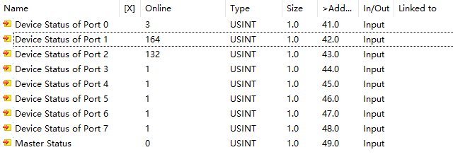
①PORT0 is configured with 2/2byte and connected to the IOL7-16CB-M12 module. The connection is normal, so the status is 3;
②PORT1 is configured with 2/2byte, but no IO-Link slave is connected, so the status is 164 (0XA4);
③PORT2 is configured with 1 byte and connected to the IOL7-16CB-M12 module. The master detects the IO-Link slave, but the process data length is incorrect, so the status is 132 (0x84);
④PORT3-PORT7 are configured in DI mode, so the status is 1.
These are the common states. As for other combinations, such as watchdog exception, cache overflow, etc., we can judge by looking up the table.